The OpenGL Pipeline Newsletter - Volume 004
Transforming OpenGL Debugging to a “White Box” Model
The OpenGL API is designed to maximize graphics performance. It is not designed for ease of debugging. When a developer works on top of OpenGL, he sees the graphics system as a "black box;" the program issues thousands of API calls into it and "magically" an image comes out of the system. But, what happens when something goes wrong? How does the developer locate the OpenGL calls that caused the problem?
In this article we will demonstrate how gDEBugger transforms OpenGL application debugging tasks from a black box model to a white box model, letting the developer peer into OpenGL to see how individual OpenGL commands affect the graphics system.
State variable related problems
An OpenGL render context is a huge state variable container. These state variables, located inside the graphics system, are treated as "global variables" that are repeatedly queried and changed by numerous OpenGL API functions and mechanisms. However, when using a general purpose debugger, a developer cannot view state variable values, cannot put data breakpoints on state variables, and, at least in Microsoft Visual Studio®, cannot put breakpoints on OpenGL API functions that serve as their high-level access functions. This black box model makes it hard to locate state variable related problems.
Using gDEBugger's OpenGL State Variables view, a developer can select OpenGL state variables and watch their values interactively.

For example, if a program renders an object, but it does not appear in the rendered image, the developer can break the debugged application run when the relevant object is being rendered and watch the related OpenGL state variable values (GL_MODELVIEW_MATRIX, GL_PROJECTION_MATRIX, GL_VIEWPORT, etc.). After locating the state variable values that appear to cause the problem, the developer can put API breakpoints on their access functions (glRotatef, glTranslatef, glMultMatrixf, etc.) and use the Call Stack and Source Code views to locate the scenario that led to the wrong state variable value assignment.

Some OpenGL mechanisms use more than just a few OpenGL state variables. For debugging these mechanisms, gDEBugger offers a State Variables Comparison Viewer. This viewer allows a developer to compare the current state variable values to either:
- The OpenGL default state variable values.
- The previous debugger suspension values.
- A stored state variable value snapshot.

For example, if a game has a mode in which a certain character's shading looks fine, and another mode in which the character's shading looks wrong, the developer can:
- Break the game application run when the character is rendered fine.
- Export all state variables and their values into a "state variable snapshot" file.
- Break the application run again when the character is rendered incorrectly.
- gDEBugger's Comparison Viewer will automatically compare the OpenGL's state variable values to the exported state variable snapshot file values.
If, for example, the game does not have a mode in which the character is rendered fine, the developer can:
- Break the game application run when the character is being rendered.
- gDEBugger's Comparison Viewer will automatically compare the OpenGL's state variable values to the default OpenGL values.
Displaying only the state variable values that were changed by the game application helps the developer track the cause of the problem.
Breaking the debugged application run
In the previous section, we asked the developer to "Break the game application run when the character is being rendered." This allows the developer to view state variable values, texture data, etc. when a certain object is being rendered. gDEBugger offers a few mechanisms to do that:
- API function breakpoints: The Breakpoint dialog lets a developer choose OpenGL / ES, WGL, GLX, EGL and extension functions breakpoints.
- The Draw Step command allows a developer to advance the debugged application process to the next OpenGL function call that has"visible impact" on the rendered image.
- The Interactive Mode Toolbar enables viewing of the graphics scene as it is being rendered, in full speed or in slow motion mode. This is done by forcing OpenGL to draw into the front color buffer, flushing the graphics pipeline after each OpenGL API function call and adding the desired slow motion delay.

Texture related problems
gDEBugger's Textures Viewer allows viewing a rendering contexts' texture objects, their parameters and the texture's loaded data as an image. Bound textures and active textures (those whose bind targets are enabled) are marked. This helps the developer to pinpoint texture related problems quickly and easily.

Program and shader related problems
gDEBugger's Shaders Source Code Editor displays a list of programs and shaders allocated in each rendering context. The editor view displays a shader's source code and parameters, a program's parameters, a program's attached shaders, and its active uniform values. The editor also allows editing shader source code, recompiling shaders, and linking and validating programs "on the fly." These powerful features save development time required for developing and debugging GLSL program and shader related problems.

We hope this article demonstrated how gDEBugger transforms the OpenGL debugging task to a white box model, minimizing the time required for finding those "hard to catch" OpenGL-related bugs and improving your program's quality and robustness.
Yaki Tebeka, Graphic Remedy
CTO & Cofounder
Editor's Note: You'll remember from our first edition that Graphic Remedy and the ARB have teamed up to make gDEBugger available free to non-commercial users for a limited time.
Another Object Lesson
The OpenGL Longs Peak object model is substantially defined now, and we have a good notion of what a Longs Peak program will look like at a high level. Many smaller details are still being filled in, but after reading this article you should understand Longs Peak in considerable detail. For a background refresher, refer to "The New Object Model" in OpenGL Pipeline Volume 002, and "Using the Longs Peak Object Model" in OpenGL Pipeline Volume 003.
What's In A Namespace? Or, a GL by any other prefix would smell as sweet.
An important decision is that the OpenGL Longs Peak API will exist in a new namespace. Originally we thought Longs Peak could continue to use "gl" prefixed functions, "GL" prefixed types, and "GL_" prefixed tokens, but as we wrote up object specifications, we realized there were too many collisions. For example, both OpenGL 2.1 and Longs Peak have a Map Buffer entry point, but they take different parameters. We haven't chosen the namespace prefix yet; it's a marketing and branding issue, not a technical issue. As a placeholder until that's decided, we're using "lp" as the prefix.
The Object Hierarchy
The objects defined in Longs Peak fall into several different categories depending on their behavior and semantics. In a true object-oriented language binding of the API, these categories would be abstract classes from which the concrete classes inherit behavior. Since our C API doesn't support inheritance, the categories are useful primarily as a conceptual tool for understanding the API. In any event, the categories are as follows:
- Templates are client state, meaning they exist in the client(application) address space.All the other categories are server state, existing in the Longs Peak driver address space. Templates are fully mutable,meaning that any of their properties can be changed at any time; this makes it easier to reuse them for generating multiple objects. Templates, and the APIs to create and use them, are described more fully in OpenGL Pipeline 003.
- State Objects contain a group of closely related attributes defining the behavior of some part of the graphics pipeline. They are fully immutable once created, which allows the driver to pre-cache derived state and otherwise optimize use of these objects, and they may be shared by multiple contexts.State objects are typically small. State object classes described below include format objects, shader objects, and texture filter objects.
- Data Objects have an immutable structure (organization) defined when they are created, and a fully mutable data store filling out that structure. They may be shared by multiple contexts, although there are some remaining issues regarding when changes made in one context to the data store of an object will be visible to another context using the same object. Data object classes described below include buffer objects, image objects, and several types of sync objects (fences and queries).
- Container Objects have one or more mutable attachments, which are references to other data, state, or container objects. They also have immutable attachment properties, which describe how to interpret their attachments. Container objects may not be shared by multiple contexts, mostly because the side effects of changing their attachments may be costly.For example, changing a shader attachment of a program object in use by another context could invalidate the state of that context at worst, and force time-consuming and unexpected relinking and validation at best. Container object classes described below include frame buffer objects, program objects, and vertex array objects.
Concrete Object Descriptions
Each of the concrete object classes mentioned above is explained in somewhat more detail here. The descriptions are organized according to the dependencies of the object graph, to avoid backwards references.
Format Objects fully resolve data formats that will be used in creating other types of objects. Such an object's defined usage must either match or be a subset of the usage supported by its format object. Format objects are a powerful generalization of the internal format parameter used in specifying texture and pixel images in OpenGL 2.1. In addition to the raw data format, format objects include:
- intended usage: pixel, texture, and/or sample image, and which texture dimensionalities (1D, 2D, 3D, cube map, and array), vertex, and/or uniform buffer
- minimum and maximum allowed texture or pixel image size
- mipmap pyramid depth and array size
- and whether data can be mipmapped, can be mapped to client address space, or is shareable.
Buffer Objects replace vertex arrays and pixel buffers, texture images, and render buffers from OpenGL 2.1. There are two types of buffer objects. Unformatted buffers are used to contain vertex data (whose format and interpretation may change depending on the vertex buffer object they're bound to) or uniform blocks used by shaders. Images are formatted buffers with a size, shape (dimensionality), and format object attachment. Changing buffer contents is done with APIs to load data (lpBufferData and lpImageData[123]D) and to map buffers in and out of client memory with several options allowing considerable flexibility in usage. See the article "Longs Peak Update: Buffer Object Improvements" earlier in this issue for more details.
Texture Filter Objects replace the state set with glTexParameter in OpenGL 2.1 controlling how sampling of textures is performed, such as minification and magnification filters, wrap modes, LOD clamps and biases, border colors, and so on. In Longs Peak, texture images and texture filters have been completely decoupled; a texture filter can be used with many different image objects, and an image can be used with many different texture filter objects.
Shader Objects are a (typically compiled) representation of part or all of a shader program, defined using a program string. A shader object may represent part or all of a stage, such as vertex or fragment, of the graphics pipeline.
Program Objects are container objects which link together one or more shader objects and associate them with a set of images, texture filters, and uniform buffers to fully define one or more stages in the programmable graphics pipeline. There is no incremental relinking; if a shader needs to be changed, simply create a new program object.
Frame buffer Objects are containers which combine one or more images to represent a complete rendering target. Like FBOs in OpenGL 2.1, they contain multiple color attachments, as well as depth and stencil attachments. When image objects are attached to an FBO, a single 2D image must be selected for attachment. For example, a 3D mipmap could have a particular mipmap level and Z offset slice selected, and the resulting 2D image attached as a color attachment. Similarly, a specific cubemap face could be selected and attached as a combined depth/stencil attachment. Each attachment point has an associated format object for determining image compatibility. When an image is bound to an FBO attachment, the format object used to create the image and the format object associated with the attachment point must be the same format object or validation fails. This somewhat draconian constraint greatly simplifies and speeds validation.
Vertex Array Objects are containers which encapsulate a complete set of vertex buffers together with the interpretation (stride, type, etc.) placed on each of those buffers. Geometry is represented in Longs Peak with VAOs, and unlike OpenGL 2.1, VAOs are entirely server state. That means no separate client arrays or enables! It also becomes very efficient to switch sets of vertex buffers in and out, since only a single VAO need be bound -- in contrast to the many independent arrays, and their interpretation, that have to be set in OpenGL 2.1 when switching VAOs. (The vendor extension GL_APPLE_vertex_array_object provides similar efficiency today, but is only available in Apple's implementation of OpenGL.)
Sync Objects are semaphores which may be set, polled, or waited upon by the client, and are used to coordinate operations between the Longs Peak server and all of the application threads associated with Longs Peak contexts in the same share group. Two subclasses of sync objects exist to date. Fence Syncs associate their semaphore with completion of a particular command (set with lpFence) by the graphics hardware, and are used to indicate completion of rendering to a texture, completion of object creation, and other such events. Query Syncs start a region with lpBeginQuery, and keep count of fragments rendered within that region. After lpEndQuery is called to end the query region, the semaphore is signaled once the final fragment count is available within the query object. In the future we will probably define other types of syncs associated with specific hardware events -- an example would be a sync associated with monitor vertical retrace -- as well as ways to convert syncs into equivalent platform-specific synchronization primitives, such as Windows events or pthreads semaphores.
The remaining objects making up Longs Peak are still being precisely defined. They are likely to include: display list objects, which capture the vertex data resulting from a draw call for later reuse; per-sample operation objects, which capture the remaining fixed-functionality state used for scissor test, stencil test, depth test, blending, and so on; and perhaps a "miscellaneous state" object containing remaining bits of state that don't have an obvious better home, such as edge flag enables, point and line smooth enables, polygon offset parameters, and point size.
Context is Important
-- with apologies to J.R.R. Tolkien
Just as in OpenGL 2.1, the Longs Peak graphics context encapsulates the current state of the graphics pipeline. Unlike OpenGL 2.1, most context state is encapsulated in attributes of server objects. A small number of objects are required to define the pipeline state. These objects are bound to the context (see figure 1); changing a binding to refer to another object updates the graphics hardware state to be consistent with that object's attributes.
Changing state by binding objects can be very efficient compared to the OpenGL 2.1 model, since we are changing large groups of state in one operation, and much of that state may have already been pre-validated while constructing the object being bound. This approach will also be useful for applications and middleware layers performing complex state management. It is both more general and more powerful than either the glPushAttrib/glPopAttrib commands or encapsulating state changes in GL display lists, which are the only ways to change large groups of state in one operation today.

Figure 1: Graphics Context Bindings. The Longs Peak context contains bindings for geometry (a vertex array object), programs (a program object), a rendering target (framebuffer object), sample operations state, and remaining fixed-functionality state affecting rasterization, hints and other miscellaneous state. In this diagram, yellow objects are containers, green objects are state objects, blue objects are data objects, red blocks represent attributes of container and state objects, and arrows represent attachments to objects or bindings to the context. The context itself, while not strictly speaking an object, is shown in yellow-red to indicate that it takes on aspects of a container object.
View Closeup
Drawing Conclusions
Once all required objects are bound to the context, we can draw geometry. The drawing call looks very much like the OpenGL 2.1 glDrawArrays, but combines multiple draw array and primitive instancing parameters into a single call:
void lpDrawArrays(LPenum mode, LPint *first,
                  LPint *count, LPsizei primCount,
                  LPsizei instanceCount)
mode is the primitive type, just as in OpenGL 2.1. first and count define the range of indices to draw. primCount ranges are specified, so count[0] vertices starting at index first[0] will be drawn from the currently bound vertex array object and passed to the vertex program. Then count[1] vertices starting at index first[1], ending with count[primCount-1] vertices starting at index first[primCount-1]. Finally, instanceCount is used for geometry instancing; the entire set of ranges will be drawn instanceCount times, each time specifying an instance ID available to the vertex shader, starting at 0 and ending at instanceCount-1.
A similar variation of glDrawElements is also provided:
void lpDrawElements(LPenum mode, LPsizei *count,
                    LPsizeiptr *indices,
                    LPsizei primCount,
                    LPsizei instanceCount)
The drawing calls are among the small number of Longs Peak entry points that do not take an object as an argument, since all the objects they use are already bound to the graphics context.
Outline for Success
-- Charles Barkley
Finally, we've reached the point of outlining a Longs Peak sample program. The outline is not intended to be detailed source code, just to give a sense of the steps that will need to be taken to fully define the objects required for rendering. While this initialization looks complex, most of it is simple "boilerplate" code that can readily be encapsulated in utility libraries or middleware such as GLUT. It is also likely that at least some of the required objects can be predefined by the driver; for example, if the application is rendering to a window-system provided drawable, then a "default framebuffer object" will be provided.
// Create a framebuffer object to render to
// This is the fully general form for offscreen
// rendering, but there will be a way to bind a window-
// system provided drawable as a framebuffer object, or
// as the color image of an FBO, as well.
LPformat cformat, dformat, sformat = { create format
objects for color, depth, and stencil buffers
respectively }

LPframebuffer fbo = { create a framebuffer object,
specifying cformat, dformat, and sformat as the
required formats of color buffer 0, the depth buffer,
and the stencil buffer respectively }

LPbuffer cimage, dimage, simage = { create image
objects, specifying cformat, dformat, and sformat as
the formats of the color image, depth image, and
stencil image respectively }

Attach cimage, dimage, and simage to fbo at its color
buffer 0, depth buffer, and stencil buffer attachment
points respectively

// Create a program object to render with
LPshader vertshader, fragshader = { create shader
objects for the vertex and fragment shader stages,
specifying the shader program text for each stage as
an attribute of the respective shader object}

LPprogram program = { create program object,
specifying vertshader and fragshader as attributes of
the program object}

LPbuffer vertbuffer, fragbuffer = { create unformatted
buffer objects for the uniform storage used by the
vertex and fragment shaders, respectively }

Attach vertbuffer and fragbuffer to program as the
backing store for the uniform partitions of the vertex
and fragment shaders, respectively

// Create vertex attribute arrays to render with
LPbuffer attribs = { create an unformatted buffer
object containing all the attribute data required by
the bound programs }

LPvertexArray vao = { create a vertex array object
with specified size/type/stride/offset attributes for
each required attribute array }

Attach attribs to vao at each attachment point for a
required attributes

// Create miscellaneous required state objects
LPsampleops sampleops = { create sample operations
object with specified fixed-function depth test,
stencil test, blending, etc. attributes }

LPmiscstate misc = { create "miscellaneous state"
object with specified rasterization settings, hints,
etc. }

// Bind everything to the context
lpBindVertexArray(vao);
lpBindProgram(program);
lpBindFramebuffer(fbo);
lpBindSampleops(sampleops);
lpBindMiscState(misc);

// Finally, all required objects are defined and we
// can draw a single triangle (or lots of them)
LPint first = 0, count = 3;
lpDrawArrays(LP_TRIANGLES, &first, &count, 1, 1);
While we still have a lot of work to do, and the final details may differ slightly, the ARB has now defined the overall structure of the Longs Peak API and the organization and definition of the object classes in the API. We'll continue to show you details of Longs Peak in future issues of OpenGL Pipeline, and when Longs Peak is released, we’ll expand these articles into a tutorial and sample code in the ARB's online SDK.
Jon Leech
OpenGL Spec Editor / ARB Ecosystem TSG Chair
(Subtitles in this article are thanks to the late-night availability of Google and www.brainyquote.com)
Longs Peak Update: Buffer Object Improvements
Longs Peak offers a number of enhancements to the buffer object API to help streamline application execution. Applications that are able to leverage these new features may derive a considerable performance benefit. In particular they can boost the performance of applications that have a lot of dynamic data flow in the form of write-once/draw-once streamed batches, procedurally generated geometry, or frequent intra-frame edits to buffer object contents.
Under OpenGL 2.1, there are two ways to transfer data from the application to a buffer object: the glBufferData/glBufferSubData calls, and the glMapBuffer/glUnmapBuffer calls. The latter themselves do not transfer any data but instead allow the application temporary access to read and write the contents of a buffer object directly. The Longs Peak enhancements described here are focused on the latter style of usage.
The behavior of glMapBuffer is not very complicated under OpenGL 2.1: it will wait until all pending drawing activity using the buffer in question has completed, and it will then return a pointer representing the beginning of the buffer, implicitly granting access to the entire buffer. Once the application has finished reading or writing data in the buffer, glUnmapBuffer must be called to return control of the storage to GL. This model is straightforward and easy to code to, but can hold back performance during some usage patterns. The usage patterns of interest are strongly centered on write-only traffic from the application, and the enhancements to the Longs Peak API reflect that.
Longs Peak will allow the application to exercise tighter control over the behavior of glMapBuffer (tentatively referred to as lpMapBuffer), by offering these new requests:
- mapping only a specified range of a buffer
- strict write-only access
- explicit flushing of altered/written regions
- whole-buffer invalidation
- partial-buffer invalidation
- non-serialized access
An application may benefit from using some or all of the above techniques. They're listed above in roughly increasing order of challenge for the developer to utilize correctly; getting the maximum performance may take more developer work and testing, depending on how application code is structured. Let's look at each of the options in more detail. Each is exposed via an individual bit flag in the access parameter to the lpMapBuffer call.
Sub-range mapping of a buffer: Under OpenGL 2.1 it was not possible to request access to a limited section of a buffer object; mapping was an “all or nothing” operation. One side effect of this is that GL has no way to know how much data was changed before unmapping, whether it involves a single range of data or potentially multiple ranges of data. In Longs Peak, by explicitly mapping sub-ranges of a buffer, the application can provide useful information to help accelerate the delivery of those edits to the buffer contents.
For example, if the application maintains a multi-megabyte vertex buffer and wishes to change a few kilobytes of localized data, it can map just the area of interest, write any changes to it, and then unmap. On implementations where altered data ranges must be copied or mirrored to GPU storage, the work at unmap time is thereby reduced significantly.
While in some cases an application may be able to achieve the same partial edit to a large buffer by using glBufferSubData, that technique assumes the original data exists in a readily copyable form. This enhancement to the lpMapBuffer path allows more efficient partial edits to a buffer object even when the CPU is sourcing the data directly via some algorithm, such as a decompression technique or procedural animation system (particles, physics, etc.). The application can map the range of interest, use the pointer as the target address for the code actually writing the finished data, and then unmap.
Write-only access: While a request of write-only access was possible in GL2, reading from those mappings was discouraged in the spec as likely to be slow or capable of causing a crash. Under Longs Peak this is even more strongly forbidden; reading from a write-only mapping may either crash or return garbage data even if the read succeeds. If there is any need to read from a mapped buffer in a Longs Peak program, you absolutely must request read access in the access parameter to lpMapBuffer.
By defining this behavior more strictly we can enhance the notion of one-way data flow from CPU to memory to GPU and free up the driver to do some interesting optimizations, the net effect being that lpMapBuffer can return more quickly with a usable pointer for writing when needed. Write-only access is especially powerful in conjunction with one or more of the options described below.
Explicit flushing: In some use cases it can be beneficial for the application to map a range of a buffer representing the “worst case” size needs for the next drawing operation, then write some number of vertices up to that amount, and then unmap. Normally this would imply to GL that all of the data in the mapped range had been changed. But by requesting explicit flushing, the application can undertake the responsibility of informing GL which regions were actually written. Use of this option requires the application to track precisely which bytes it has written to, and to tell GL where those bytes are prior to unmap through use of the lpFlushMappedData API.
For some types of client code where vertices are being generated procedurally, it can be difficult to predict the number of vertices generated precisely in advance. With explicit flush, the application can “reserve” a worst-case-sized region at map time, and then “commit” the portion actually generated through the lpFlushMappedData call, prior to unmap.
This ability to convey precisely how much data was written (and where) has a number of positive implications for the driver with respect to any temporary memory management it may need to do in response to the request. While an application can and should use the map-time range information to constrain the amount of storage being manipulated, explicit flushing allows for additional control if that amount cannot be precisely predicted at map time.
This is another case where the same net effect could be accomplished by using a separate temp buffer for the initial data generation, followed by a call to glBufferSubData. However, being able to write the finished data directly into the mapped region can eliminate a copying step for the application and also potentially reduce processor cache pollution depending on the implementation.
Whole-buffer invalidation: This is analogous to the glBufferData(NULL) idiom from OpenGL 2.1, whereby a new block of uninitialized storage is atomically swapped into the buffer object, but the old storage is detached for the driver to release at a later time after pending drawing operations have completed -- also known as “buffer orphaning.” Since Longs Peak no longer allows the glBufferData(NULL) idiom, this functionality is now provided as an option to the lpMapBuffer call. This is especially useful for implementing efficient streaming of variable sized batches; an application can set up a fixed size buffer object, then repeatedly fill and draw at ascending offsets -- packing as many batches as possible into the buffer -- then perform a full buffer invalidation and start over at offset zero.
Partial-buffer invalidation: This option can and should be invoked when the application knows that none of the data currently stored within the mapped range of a buffer needs to be preserved. That is, the application’s intent is to overwrite all or part of that range, and only the newly written data is expected to have any validity upon completion. This option is only usable in conjunction with write-only access mode. It has a number of positive implications for performance, as it releases the driver from the requirement of providing any valid view of the existing storage at map time. Instead it is free to provide scratch memory in order to return a usable pointer to the application more quickly.
Generally speaking, a program can and should make use of both partial and whole buffer invalidation, but the usage frequency of the former is expected to be much higher. Restated, partial invalidation is useful for efficiently accumulating individual batches of CPU-sourced data into a common buffer, whereas whole buffer invalidation should be invoked when one buffer fills up and a fresh batch of storage is needed. Whole buffer invalidation, like glBufferData(NULL) in OpenGL 2.1, enables the application to perform these hand-offs without any need for sync objects, fences, or blocking.
Non-serialized access: This option allows an application to assume complete responsibility for scheduling buffer accesses. When this option is engaged, lpMapBuffer may not block if there is pending drawing activity on the buffer of interest. Access may be granted without consideration for any such concurrent activity. Another term for this behavior is "non-blocking mapping." If you have written code for OpenGL 2.1 and run into stalls in glMapBuffer, this option may be of interest.
When used in conjunction with write-only access and partial invalidation, this option can enable the application to efficiently accumulate any number of edits to a common buffer interleaved with draw calls using those regions, keeping the drawing thread largely unblocked and effectively decoupling CPU progress from GPU progress. On contemporary multi-core-aware implementations where multiple frames' worth of drawing commands may be enqueued at any given moment, the impact of being able to interleave mapped buffer access with drawing requests (without blocking the application) can be quite significant.
An application can only safely use this option if it has taken the necessary steps to ensure that regions of the buffer being used by drawing operations are not altered by the application before those operations complete. This can be accomplished using proper use of sync objects, or by enforcing a write-once policy per region of the buffer. A developer must not set this bit and expect everything to keep working as-is; careful thought must go into analysis of existing access/drawing patterns before proceeding with the use of this technique. The caution level on the part of the developer must be very high, but the potential rewards are also significant.
As the Longs Peak spec is still evolving and minor naming or API changes may yet be made, some of the terminology above could change before the final spec is drafted and released. This article is intended to offer a “sneak peek” at the types of improvements under consideration. Please share your questions and feedback with us on the OpenGL forums.
T. Hunter
Object Model Technical SubGroup Contributor
Shaders Go Mobile: Announcing OpenGL ES 2.0
Shaders Go Mobile: Announcing OpenGL ES 2.0
It’s here at last! At the Game Developers Conference in March, the OpenGL ES Working Group announced the release of OpenGL ES 2.0, the newest version of OpenGL for mobile devices. OpenGL ES 2.0 brings shader-based rendering to cell phones, set-top boxes, and other embedded platforms. The new specification has been three years in the making – work actually started before the release of our last major release, OpenGL ES 1.1. What took so long? When we created the ES 1.x specifications, we were using mature technology, following paths that the OpenGL ARB had thoroughly explored in older versions of the desktop API. With OpenGL ES 2.0, we moved closer to the cutting edge, so we had less experience to guide us. But the work is done now. We’re very pleased with what we came up with, and excited to have the specification released and silicon on the way. We think you’ll agree that it was worth the wait.
A Lean, Mean, Shadin’ Machine…
Like its predecessors, OpenGL ES 2.0 is based on a version of desktop OpenGL – in this case, OpenGL 2.0. That means, of course, that it supports vertex and fragment shaders written in a high-level programming language. But almost as interesting as what ES 2.0 has, is what it doesn’t have. As I said in the OpenGL ES article in OpenGL Pipeline #3, one of the fundamental design principles of OpenGL ES is to avoid providing multiple ways of achieving the same goal. In OpenGL 2.0 on the desktop, you can do your vertex and fragment processing in shaders or you can use traditional fixed-functionality transformation, lighting, and texturing controlled by state-setting commands. You can even mix and match, using the fixed-functionality vertex pipeline with a fragment shader, or vice versa. It’s powerful, flexible, and backward compatible; but isn’t it, perhaps, a little bit… redundant?
One of the first (and toughest) decisions we made for OpenGL ES 2.0 was to break backward compatibility with ES 1.0 and 1.1. We decided to interpret the “avoid redundancy” rule to mean that anything that can be done in a shader should be removed from the fixed-functionality pipeline. That means that transformation, lighting, texturing, and fog calculation have been removed from the API. We even removed alpha test, since you can perform it in a fragment shader using discard. Depth test, stencil test, and blending are still there, because you can’t perform them in a shader; even if you could read the frame buffer, these operations must be executed per sample, whereas fragment shaders work on fragments.
Living without the fixed-functionality pipeline may seem a little scary, but the advantages are enormous. The API becomes very simple and easy to learn – a handful of state-setting calls, plus a few functions to load and compile shaders. At the same time, the driver gets a lot smaller. An OpenGL 2.0 driver has to do a lot of work to let you switch back and forth smoothly between fixed-functionality and programmable mode, access fixed-functionality state inside your shaders, and so on. Since OpenGL ES 2.0 has no fixed-functionality mode, all of that complexity goes away.
…with Leather Seats, AC, and Cruise Control
OpenGL ES 2.0 lacks the fixed-functionality capability of OpenGL ES 1.x, but don’t get the impression that it is a stripped-down, bare-bones API. Along with the shader capability, we’ve added many other new features that weren’t available in ES 1.0 or 1.1. Among them are:
More Complex Vertices
ES 2.0 vertex shaders can declare at least eight general-purpose vec4 attributes, versus the five dedicated vertex arrays of ES 1.1 (position, normal, color, texcoord0, texcoord1). On the output side, the vertex shader can send at least eight vec4 varyings to the fragment shader.Texture Features Galore
OpenGL ES 2.0 implementations are guaranteed to provide at least eight texture units, up from two in ES 1.1. Dependent texturing is supported, as are non-power-of-two texture sizes (with certain limitations). Cube map textures are added as well, because what fun would fragment shaders be without support for environment mapping, global illumination maps, directional lookup tables, and other cool hacks?Stencil Buffer
All ES 2.0 implementations provide at least one configuration with simultaneous support for stencil and depth buffers.Frame Buffer Objects
OpenGL ES 2.0 supports a version of the EXT_framebuffer_object extension as a mandatory core feature. This provides (among other things) an elegant way to achieve render-to-texture capabilities.Blending
OpenGL ES 2.0 extends the options available in the fixed-functionality blending unit, adding support for most of BlendEquation and BlendEquationSeparate.Options
Along with the ES 2.0 specification, the working group defined a set of options and extensions that are intended to work well with the API. These include ETC1 texture compression (contributed by Ericsson), 3D textures, NPOT mip-maps, and more.
The Shader Language
OpenGL ES 2.0 shaders are written in GLSL ES, a high-level shading language. GLSL ES is very similar to desktop GLSL, and it is possible (with some care, and a few well-placed #ifdefs) to write shader code that will compile under either. We’ll go over the differences in detail in a future issue of OpenGL Pipeline, and talk about how to write portable code.
Learning More
The ES 2.0 and GLSL ES 1.0 specifications are available for download at http://www.khronos.org/registry/gles/. The API document is a ‘difference specification’, and should be read in parallel with the desktop OpenGL 2.0 specification, available at http://www.opengl.org/documentation/specs/. The shading language specification is a stand-alone document.
Take it for a test drive
OpenGL ES 2.0 silicon for mobile devices won’t be available for a while yet, but you can get a development environment and example programs at http://www.imgtec.com/PowerVR/insider/toolsSDKs/KhronosOpenGLES2xSGX/. This package runs on the desktop under Windows or Linux, using an OpenGL 2.0 capable graphics card to render ES 2.0 content. Other desktop SDKs may well be available by the time you read this, so keep an eye on the Khronos home page and the resource list at http://www.khronos.org/developers/resources/opengles/. If you just want to experiment with the shading language, AMD has announced that GLSL ES will be supported in RenderMonkey 1.7, coming soon.
Tom Olson, Texas Instruments, Inc.
OpenGL ES Working Group Chair
Climbing OpenGL Longs Peak, Camp 3: An OpenGL ARB Progress Update
 Longs Peak – 14,255 feet, 15th highest mountain in Colorado. Mount Evans is the 14th highest mountain in Colorado. (Therefore, we have at least 13 OpenGL revisions to go!)
Since the last edition of OpenGL Pipeline we’ve increased our efforts even more. We held a face-to-face meeting in March and another face-to-face meeting at the end of May. Currently we’re on track to meet face-to-face six times this year, instead of the usual four! The ARB recognizes it is extremely important to get OpenGL Longs Peak and Mount Evans done. We also still meet by phone five times per week. This is a big commitment from our members, and I’m very happy and proud to see the graphics industry working together to make OpenGL the best graphics platform!
A lot has happened since the last edition of Pipeline. Below follows a brief summary of the most important advances. Other articles in this edition will go into more detail on some of the topics. Happy reading!
Maximize vertex throughput using buffer objects. Just like in OpenGL 2.1, an application can map a buffer object in OpenGL Longs Peak. Mapping a buffer object returns a pointer to the application which can be used to write (or read) data to (or from) the buffer object. In OpenGL Longs Peak the mapping is made more sophisticated, with the end result that maximum parallelism can be achieved between the application writing data into the buffer object and the GL implementation reading data out of it. Read more about this cool feature in an article later in this newsletter.
More context creation options are available. In the previous edition of OpenGL Pipeline I described how we are planning on handling interoperability of OpenGL 2.1 and Longs Peak code. As a result, the application needs to explicitly create an OpenGL Longs Peak or OpenGL 2.x context. To aid debugging, it is also possible to request the GL to create a debug context. A debug context is only intended for use during application development. It provides additional validation, logging and error checking, but possibly at the cost of performance.
The object handle model is fleshed out. We finalized all the nitty-gritty details of the object model that have to do with object and handle creation and deletion, attachment of an object to a container object, and the behavior of these operations across contexts. Here is a brief summary:
- The GL creates handles, not the application, as can be the case in OpenGL 2.1. This is done in the name of efficiency.
- Object creation can be asynchronous. This means that it is possible that the creation of an object happens later in time than the creation of the handle to the object. A call to an object creation routine will return the handle to the caller immediately. The GL server might not get to the creation of the actual object until later. This is again done for performance reasons. The rule that all commands are executed in the order issued still applies (within a given context). Thus, asynchronous object creation might mean that a later request to operate on an object will have to block until the object is created. Fences and queries can help determine if this will be the case.
- Object use by the GL is reference counted. Once the “refcount” of an object goes to zero, the GL implementation is free to delete the storage of the object. Object creation sets the refcount to 1.
- The application does not delete an object, but instead invalidates the object handle. The invalidation decrements the object’s refcount.
- An object’s refcount is incremented whenever it is “in use.” Examples of “in use” include attaching an object to a container object, or binding an object into the context.
- Once a handle is invalidated, it cannot be used to refer to its underlying object anymore, even if the object still exists.
Most context state will be moved into an object. We are currently pondering which state stays in the context, and which context state is moved into an object. One interesting set of state I want to highlight is the state for the per-fragment operations, described in Chapter 4 of the OpenGL 2.1 specification. This state actually applies per sample, not per fragment. Think of state such as alpha test, stencil test, depth test, etc. We expect that some time in the future hardware will be available that makes all these operations programmable. Once that happens, we’ll define another program object type, and would like to be able to just “drop it in” to the framework defined in OpenGL Longs Peak. Therefore, we are working on defining a sample operation state object that contains all this state.
We’re also working on fleshing out the draw commands as well as display lists. Good progress was made defining what the draw calls will look like. We decided to keep it simple, and largely mirror what is done in OpenGL 2.1. There will be DrawArrays, DrawElements, etc. commands that take vertex indices. In order to actually render, at least a program object, a vertex array object, and an FBO need to be bound to the context. Possibly a sample operation state object, as describe above, will also need to be bound.
You can meet the designers behind OpenGL Longs Peak and Mount Evans at Siggraph 2007 in August. The traditional OpenGL BOF (Birds of a Feather) will likely be on Wednesday evening, August 8th, from 6:00pm – 8:00pm. I hope to see you there!
In the remainder of this issue you’ll find an update from the OpenGL ES Working Group, a discussion of Longs Peak buffer object improvements, a look at the Longs Peak object model with source code samples, and an article showing how to use gDEBugger as a window exposing what’s happening within the GL.
Barthold Lichtenbelt, NVIDIA
Khronos OpenGL ARB Steering Group chair
Windows Vista and OpenGL-the Facts
 Japanese Translation (pdf)
 Simplified Chinese Translation
 April 20, 2007
The Khronos OpenGL ARB Working Group has received requests for clarification concerning the performance of OpenGL on Windows Vista. These questions are understandable as Microsoft has dramatically changed the user experience with the Windows Aero compositing desktop and introduced a completely new display driver architecture. This article will discuss how these changes affect OpenGL.
The industry now has a growing body of real-world experience in shipping OpenGL on Windows Vista and the OpenGL ARB wishes to reinforce the positive synergy between OpenGL graphics and Windows Vista in three key areas
- Windows Vista fully supports hardware accelerated OpenGL;
- OpenGL applications can benefit from Window Vista•s improved graphics resource management;
- OpenGL performance on Windows Vista is extremely competitive with the performance on Windows XP.
Windows Vista Fully Supports OpenGL
Hardware-accelerated OpenGL is fully supported on Windows Vista with the Windows Aero compositing desktop user experience - just as with Direct3D.
OpenGL hardware acceleration is handled in exactly the same way in Windows XP and Windows Vista - through an Installable Client Driver (ICD) provided by graphics card manufacturers. Without an OpenGL ICD installed, Windows XP and Windows Vista both revert to rendering OpenGL in software on the CPU rather than using GPU acceleration.
Figure 1 shows the path through which OpenGL and Direct3D applications render their output under Windows Vista. Firstly, the OpenGL or Direct3D user-mode graphics drivers take the data from the application and use the graphics hardware to render one frame of content. That frame is then presented to the Desktop Window Manager (DWM) which composites the frame into the desktop using GPU acceleration. The DWM provides the desktop compositing functionality used by the Windows Aero and Windows Standard user experiences in Windows Vista.
The DWM is a key element of the Windows Vista user experience and one of its main functions is to manage the presentation of the Windows desktop by compositing the outputs of multiple applications to the screen. As a complete 3D application in its own right, the DWM uses GPU memory and resources and places an additional load on the GPU, which impacts application graphics performance by approximately 10% for typical applications. End users should weigh the benefits of the DWM and the Windows Aero user interface against this performance cost. An easy way to experiment with a particular application is to disable the DWM, by selecting the Windows Classic or Windows Basic user interface style.
During full-screen applications, such as games, the DWM is not performing window compositing and therefore performance will not appreciably decrease.

Figure 1 - OpenGL, Direct3D and the Desktop Window Manager (DWM)
OpenGL Benefits from Improved Resource Management
The new Windows Display Driver Model (WDDM) in Windows Vista provides a firewall and the thunk layer (that handles communication between the graphics hardware/kernel mode graphics driver and the user-mode graphics driver) to increase overall system stability. This architecture differs from Windows XP, where the OpenGL ICD talked directly to the GPU hardware and handled many low-level functions, including memory management.
WDDM affords some implicit benefits for OpenGL applications. For example, graphics resources previously managed by the OpenGL ICD, such as video memory, are now virtualized by the operating system. When multiple applications are running, the OpenGL ICD exposes maximum texture storage capacity to each application and Windows Vista takes care of resource allocation and scheduling, resulting in more efficient use of resources across applications.
OpenGL Performance is Competitive on Windows Vista
Some have suggested that OpenGL performance on Windows Vista is poor compared to Windows XP. This is not the case.
A comparison between the performance on Windows XP and Windows Vista of the SPECviewperf professional OpenGL benchmark, two OpenGL game benchmarks, and two Direct3D game benchmarks are presented below.
Professional OpenGL Application Performance
The SPECviewperf figure below shows that the graphics performance of professional OpenGL applications on Windows Vista is very close to that on Windows XP. SPECviewperf runs in a window, and on Windows Vista the DWM was turned off, by selecting the Windows Classic color scheme, to achieve maximum graphics performance. These numbers are extremely impressive, given that the WDDM is a radical departure from the Display Driver model on Windows XP and the new Windows Vista drivers have not yet benefited from the years of tuning and optimization that the Windows XP OpenGL drivers have undergone. Software developers and graphics card manufacturers have had access to production-ready Windows Vista since November 2006, and graphics performance on Windows Vista will continue to improve over time as the drivers mature. As with any version of Microsoft Windows however, it is important to download the latest drivers from the graphics card vendor - particularly in the early lifetime of a new operating system.

If DWM were enabled through enabling Windows Aero - performance would drop by about 10%. For many users this tradeoff is worthwhile in order to use the more advanced user interface.
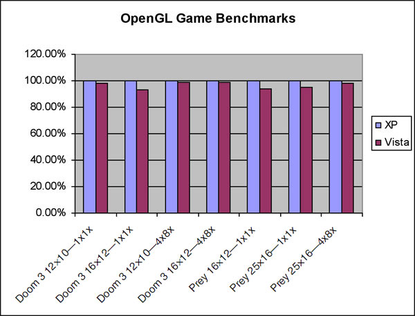
OpenGL Game Performance
The Doom3 (demo1) and Prey (move.demo) figures below show that Windows Vista performance for full-screen OpenGL games is comparable to the performance delivered on Windows XP. As these applications are full screen, DWM is not active and there is no performance drop in Windows Aero.
Direct3D Game Performance
The diagram below shows how the Direct3D games Half Life 2 Episode One (demo1) and Oblivion (Outdoor, HDR off) perform on Windows XP and Windows Vista. These numbers were obtained on the same system and same driver versions as the OpenGL benchmarks. In all cases the benchmarks were run in full-screen mode.
These figures show that Windows Vista performance for full-screen Direct3D games is comparable to the performance delivered on Windows XP • just as for OpenGL. As these applications are full screen, DWM is not active and there is no performance drop in Windows Aero.
These results confirm that both Direct3D and OpenGL are excellent 3D APIs for Windows Vista.

Conclusion
OpenGL is fully integrated into the Windows Vista display architecture just like Direct3D -both interfaces are first-class graphics API citizens. OpenGL hardware acceleration is available on Windows Vista through highly optimized drivers provided by the graphics hardware vendor just as on Windows XP. OpenGL applications can benefit from the improved resource management provided by Windows Vista. OpenGL performance on Windows Vista is extremely competitive compared to Windows XP and will rapidly improve as support for this new operating system matures. The enhanced Windows Aero user interface can decrease graphics intensive application performance by about 10% but this performance drop can be eliminated by selecting Windows Classic or Windows Basic user interface style or using full-screen applications. To ensure maximum performance and stability on Windows Vista, users should regularly check for driver upgrades from their graphics hardware supplier.
The third edition of the OpenGL Pipeline Newsletter, an OpenGL ARB publication, has included an article written by NVIDIA for software developers with tips to get the maximum out of their OpenGL application on Windows Vista. This article can be found here: http://www.opengl.org/pipeline/article/vol003_7/
For questions about this article, or about OpenGL in general, please contact Barthold Lichtenbelt at blichtenbelt@nvidia.com, Khronos OpenGL ARB Working Group chair.
References
General overview “What is Aero”
Overview of how DX9, DX10, GDI, OpenGL and the DWM are architected under the WDDM
OpenGL ARB article with tips for ISVs developing OpenGL applications on Windows Vista
Game performance results were obtained on an AMD Athlon 64 FX-62 2.8 GHz system with a NVIDIA GeForce 7900GTX graphics card, with driver version 97.73 for Windows XP, and 101.20 for Windows Vista, running in full-screen mode. The SPECviewperf results were obtained on a Dual Xeon 3.0 GHz system with a NVIDIA Quadro FX 5500 graphics card, with driver version 91.36 for Windows XP, and 100.72 for Windows Vista.
OpenGL is a registered trademark of Silicon Graphics Inc. SPECviewperf® is a registered trademark of the Standard Performance Evaluation Corporation, www.spec.org. All other product names, trademarks, and/or company names are used solely for identification and belong to their respective owners.
Optimize Your Application Performance
In the previous article, “Clean your OpenGL usage using gDEBugger,” we demonstrated how gDEBugger can help you verify that your application uses OpenGL correctly and calls the OpenGL API commands you expect it to call. This article will discuss the use of ATI and NVIDIA performance counters together with gDEBugger's Performance Views to locate graphics pipeline performance bottlenecks.
Graphics Pipeline Bottlenecks
The graphics system generates images through a pipelined sequence of operations. A pipeline runs only as fast as its slowest stage. The slowest stage is often called the pipeline bottleneck. A single graphics primitive (for example, a triangle) has a single graphic pipeline bottleneck. However, the bottleneck may change when rendering a graphics frame that contains multiple primitives. For example, if the application first renders a group of lines and afterwards a group of lit and shaded triangles, we can expect the bottleneck to change.
The OpenGL Pipeline
The OpenGL pipeline is an abstraction of the graphics system pipeline. It contains stages, executed one after the other. Such stages are:
- Application: the graphical application, executed on the CPU, calls OpenGL API functions.
- Driver: the graphics system driver runs on the CPU and translates OpenGL API calls into actions executed on either the CPU or the GPU.
- Geometric operations: the operations required to calculate vertex attributes and position within the rendered 2D image space. This includes: multiplying vertices by the model-view and projection matrices, calculating vertex lighting values, executing vertex shaders, etc.
- Raster operations: operations operating on fragments / screen pixels: reading and writing color components, reading and writing depth and stencil buffers, performing alpha blending, using textures, executing fragment shaders, etc.
- Frame buffer: a memory area holding the rendered 2D image.
Some of the pipeline stages are executed on the CPU; other stages are executed on the GPU. Most operations that are executed on top of the GPU are executed in parallel.
Remove Performance Bottlenecks
As mentioned in the “Graphics Pipeline Bottlenecks” section, the graphics system runs only as fast as its slowest pipeline stage, which is often called the pipeline bottleneck. The process for removing performance bottlenecks usually involves the following stages:
- Identify the bottleneck: Locate the pipeline stage that is the current graphic pipeline bottleneck.
- Optimize: Reduce the workload done in that pipeline stage until performance stops improving or until you have achieved the desired performance level.
- Repeat: Go back to stage 1.
Notice that after your performance optimizations are done, or after you have reached a bottleneck that you cannot optimize anymore, you can start adding workload to pipeline stages that are not fully utilized without affecting render performance. For example, use more accurate textures, perform more complicated vertex shader operations, etc.
gDEBugger Performance Graph View
gDEBugger Performance Graph view helps you locate your application's graphics pipeline performance bottlenecks; it displays, in real time, graphics system performance metrics. Viewing metrics that measure the workload done in each pipeline stage enables you to estimate the current performance pipeline bottleneck.
gDEBugger Performance Graph View helps you locate your application’s graphic pipeline performance bottlenecks. View Closeup
Such metrics are: CPU user mode and privilege mode utilizations, graphics driver idle, GPU idle, vertex shader utilization, fragment shader utilization, video memory usage, culled primitives counters, frames per seconds (per render context), number of OpenGL function calls per frame, total size of all loaded textures (in texels) and many other counters.
There is no need to make any changes to your source code or recompile your application. The performance counters will be displayed inside the Performance Graph view.
gDEBugger supports operating system performance counters (Windows and Linux), NVIDIA's performance counters via NVPerfKit, ATI's performance metrics and gDEBugger's internal performance counters. Other IHVs' counters will be supported in the future.
gDEBugger Performance Analysis Toolbar
![]() The Performance Analysis toolbar offers commands that enable you to pinpoint application performance bottlenecks by “turning off” graphics pipeline stages. If the performance metrics improve while “turning off” a certain stage, you have found a graphics pipeline bottleneck!
The Performance Analysis toolbar offers commands that enable you to pinpoint application performance bottlenecks by “turning off” graphics pipeline stages. If the performance metrics improve while “turning off” a certain stage, you have found a graphics pipeline bottleneck!
These commands include:
![]() - Eliminate Draw Commands: Identify CPU and bus performance bottlenecks by ignoring all OpenGL commands that push vertices or texture data into OpenGL. When ignoring these commands, the CPU and bus workloads remain unchanged, but the GPU workload is almost totally removed, since most GPU activities are triggered by input primitives (triangles, lines, etc).
- Eliminate Draw Commands: Identify CPU and bus performance bottlenecks by ignoring all OpenGL commands that push vertices or texture data into OpenGL. When ignoring these commands, the CPU and bus workloads remain unchanged, but the GPU workload is almost totally removed, since most GPU activities are triggered by input primitives (triangles, lines, etc).
![]() - Eliminate Raster operations: Identify raster operation bottlenecks by forcing OpenGL to use a 1x1 pixels view port. Raster operations operate per fragment or pixel. By setting a 1x1 pixel view port most raster operations will be eliminated.
- Eliminate Raster operations: Identify raster operation bottlenecks by forcing OpenGL to use a 1x1 pixels view port. Raster operations operate per fragment or pixel. By setting a 1x1 pixel view port most raster operations will be eliminated.
![]() - Eliminate Fixed Pipeline Lighting operations: Identify “fixed pipeline lighting” related calculation bottlenecks. This is done by turning off all OpenGL fixed pipeline lights. Notice that this command does not affect shaders that do not use the fixed pipeline lights.
- Eliminate Fixed Pipeline Lighting operations: Identify “fixed pipeline lighting” related calculation bottlenecks. This is done by turning off all OpenGL fixed pipeline lights. Notice that this command does not affect shaders that do not use the fixed pipeline lights.
![]() - Eliminate Textures Data Fetch operations: Identify texture memory performance bottlenecks by forcing OpenGL to use 2x2 pixel stub textures instead of the application defined textures. By using such small stub textures, the texture data fetch operation workload will be almost completely removed.
- Eliminate Textures Data Fetch operations: Identify texture memory performance bottlenecks by forcing OpenGL to use 2x2 pixel stub textures instead of the application defined textures. By using such small stub textures, the texture data fetch operation workload will be almost completely removed.
![]() - Eliminate Fragment Shader Operations: Identify fragment shader related bottlenecks by forcing OpenGL to use a very simple stub fragment shader instead of the application defined fragment shaders.
- Eliminate Fragment Shader Operations: Identify fragment shader related bottlenecks by forcing OpenGL to use a very simple stub fragment shader instead of the application defined fragment shaders.
The “Combined” Approach
Combining the Performance Analysis toolbar with the Performance Graph view gives an even stronger ability to locate performance bottlenecks. Viewing the way performance metrics vary when disabling graphics pipeline stages can give excellent hints for locating the graphics pipeline performance bottleneck.
For example, an application runs at 20 F/S and has 100% fragment shader utilization and 30% vertex shader utilization. When disabling fragment shader operations, the metrics change to 50 F/S, 2% fragment shader utilization and 90% vertex shader utilization. The “combined” approach tells us that the current bottleneck is probably the fragment shader operations. It also tells us that if we optimize and reduce the fragment shader operation workload, the next bottleneck that we will come across will probably be the vertex shader operations.
We hope this article will help you optimize the performance of your OpenGL based applications. In our next article we will talk about OpenGL's debugging model and show how gDEBugger can help you find those “hard to catch” OpenGL-related bugs.
Yaki Tebeka, Graphic Remedy
CTO & Cofounder
Editor's Note: You'll remember from our first edition that Graphic Remedy and the ARB have teamed up to make gDEBugger available free to non-commercial users for a limited time.
OpenGL and Windows Vista™
So Windows Vista is here, but what does it mean for an OpenGL user and developer? In this article we will try to give OpenGL application developers a quick peek at what to expect and the current state of OpenGL on Windows Vista.
Windows Vista supports two primary OpenGL implementations:
- Hardware manufacturers provide OpenGL ICD (installable client driver) with variable renderer string. The OpenGL version supported depends on the hardware manufacturer.
- Microsoft's software OpenGL 1.1 implementation (renderer string is GDI Generic), is clustered in higher numbered pixel formats.
Just like Windows XP, Windows Vista does not contain an OpenGL ICD "in the box." End users will need to install drivers from OEMs or video hardware manufacturers in order to access native hardware-accelerated OpenGL. These drivers can be found on the Web sites of most hardware manufacturers.
The two biggest changes that Windows Vista brings to OpenGL are:
- The new driver model, Windows Display Driver Model (WDDM), formerly known as Longhorn Display Driver Model (LDDM).
- The new Desktop Window Manager with its Desktop Compositing Engine provides 3D accelerated window composition when Windows Aero is turned on.
OpenGL and Direct3D are treated the same by Windows Vista, resulting in full integration into the OS for both APIs. For example, both Direct3D and OpenGL will get transparency and dynamic thumbnails when Windows Aero is on, and all the WDDM features (video memory virtualization, etc.) will work in a similar fashion.
Changes Introduced by the New Windows Display Driver Model
Under WDDM, Microsoft takes ownership of the virtualization of video resources at the video memory level, but also at the graphics engine level. In short, this means that multiple simultaneous graphics applications can be running in round robin as scheduled by Windows Vista's Video Scheduler and their working sets (video resources) will be paged in, as needed, by Windows Vista's Video Memory Manager.
Being that the video hardware is virtualized, user-mode components (the OpenGL ICD is one of those) no longer have direct access to that hardware, and need a kernel transition in order to program registers, submit command buffers, or know the real addresses of the video resources in memory.
Because Windows Vista controls the submission of graphic command buffers to the hardware, detecting hangs of the graphics chip due to invalid programming is now possible across the operating system. This is achieved via Windows Vista's Timeout Detection and Recovery (TDR). When a command buffer spends too long in the graphics chip (more than two seconds), the operating system assumes the chip is hung, kills all the graphics contexts, resets the graphics chip and recovers the graphics driver, in order to keep the operating system responsive. The user will then see a popup bubble notifying that the "Display driver stopped responding and has recovered."

Changes Introduced by the Desktop Window Manager
Graphics applications now have to share resources with the 3D-accelerated window manager. Each OpenGL window now requires an offscreen frontbuffer, because there's no longer direct access to the surface being displayed: the desktop. This is also true when the Desktop Windows Manager (DWM) is off.
In order for Windows Vista to perform compositing, DWM allocates an extra window-sized compositing buffer for each top-level window in the system. All these resources add up and increase the video memory footprint.
GDI is no longer hardware-accelerated, but instead rendered to system memory using the CPU. That rendering is later composed on a 3D surface in order to be shown on the desktop. The graphics hardware video driver is no longer involved in GDI rendering, which means that mixing GDI and accelerated 3D rendering in the same window is likely to produce corruption like stale or blanked 3D rendering, trails, etc. Using Microsoft's OpenGL software rendering (the first item in the four OpenGL implementations) will achieve GDI compatibility, but at the expense of rendering speed and lack of modern features.

Windows Vista running with Aero disabled. View Closeup

Windows Vista running with Aero enabled. Note the semi-transparent window decorations and the dynamic thumbnails representing the running applications. View Closeup
Windows Vista running with Aero enabled. Note the semi-transparent windows and the dynamic thumbnails representing the running applications.
What All This Means for the OpenGL ICD User
Software application companies are preparing new versions of their OpenGL applications to take advantage of the new features and fix the possible incompatibilities that Windows Vista may have introduced.
Meanwhile,
- Current Windows XP full screen OpenGL applications are likely to work, although applications that use GDI under the covers (e.g. taking screenshots using Alt+Print Screen, or some enhanced GDI mouse pointers) may not work.
- Carefully written windowed applications should also work. For those which make use of GDI and OpenGL a developer may find that the Desktop Window Manager is disabled when they launch with the message "The color scheme has been changed to Windows Vista Basic." The DWM will be turned on again when the application exits.
- For other windowed applications, if developers observe graphics corruption or lack of rendering refresh, developers may need to disable the DWM manually by switching to the "Windows Vista Basic" theme before starting the application. This also applies to an application's third-party plugins which require GDI interoperability without the application's knowledge. It is possible that some of them will cause corrupted rendering and will require developers to switch off DWM manually.
- Windowed applications that use frontbuffer rendering without ever calling glFlush or glFinish (as they should) are likely to appear completely black, because the rendering will sit forever in the offscreen frontbuffer. Not even switching the DWM off is likely to fix these, given that the offscreen frontbuffer is a requirement of the driver model itself.
- Windowed stereo rendering will not work.
- Simultaneously using graphics cards from multiple vendors will not work, given that Windows Vista only allows one WDDM driver to be loaded at the same time. Note that multi-card solutions from the same vendor (NVIDIA® SLI™ or AMD™ CrossFire™) should work.
- Memory consumption reduction schemes like Unified Depth/Backbuffer are not possible under the DWM, which increases the memory footprint of the application.
Will My Applications Run Fast?
Performance-wise, developers can expect a decrease of around 10-15% on Windows as compared to Windows XP. Applications that use problematic cases (for example, excessive flushing, or rendering to the frontbuffer, as explained later) can see a larger performance degradation. However, expect this gap to become smaller over time while the graphics hardware vendors work on further optimizing their Windows Vista WDDM drivers.
WDDM's increased memory footprint and new video memory manager approach may worsen resource-hungry scenarios. Applications which were already pushing the limits of memory consumption on Windows XP, just barely fitting, may fall off a performance cliff on Windows Vista. This is due to excessive thrashing because available system and/or video memory is now exhausted.
What All This Means for the OpenGL Developer
GDI compatibility notes
GDI usage over 3D accelerated regions is incompatible with Windows Aero, so developers have two options:
- Disable Windows Aero
- Do not use GDI on top of OpenGL rendering.
Windows Vista introduces the new pixelformat flag PFD_SUPPORT_COMPOSITION (defined in the Driver Development Kit's wingdi.h as 0x00008000). Creating an OpenGL context for a pixelformat without this flag will disable composition for the duration of the process which created the context. The flag is mutually exclusive with PFD_SUPPORT_GDI.
If a developer must use GDI on top of an OpenGL context, use the following rules:
- Create an OpenGL context using a pixelformat with GDI support (PFD_SUPPORT_GDI flag set). As this flag is mutually exclusive with PFD_SUPPORT_COMPOSITION, this will disable Aero for the lifetime of the current process.
- Don't use BeginPaint/EndPaint outside the WM_PAINT message handling.
- As on Windows XP, use the API synchronization calls whenever necessary: GdiFlush to synchronize GDI with OpenGL rendering and glFinish for the converse.
On the other hand, if a developer wants to have Windows Aero enabled with a windowed OpenGL application, use the following rules to verify that you are not inadvertently trying to mix GDI over OpenGL:
- Create an OpenGL context using a pixelformat with compositing support (PFD_SUPPORT_COMPOSITION set).
- Handle the application window's WM_ERASEBKGND by returning non-zero in the message handler (this will avoid GDI clearing the OpenGL windows' background).
- Verify that the OpenGL window has the proper clipping styles WS_CLIPCHILDREN or WS_CLIPSIBLINGS, so GDI rendering of sibling windows in the layout hierarchy is not painted over and vice versa.
- Repaint the application's windows as they are being resized rather than when the final resize happens. This will avoid interacting with GDI's xor drawing of the window border. For example, if the application has splitter bars in a four-viewport application, resize the viewports as the splitter bar is being dragged, otherwise GDI xor rendering over the OpenGL viewport will leave trails.
- Do not use GDI for xor drawing of "rubberbands" or selection highlighting over the OpenGL rendering. Use OpenGL logical operations instead.
- Do not get the desktop's DC and try to paint over it with GDI, as it will corrupt the 3D-accelerated regions.
- Under the DWM's new architecture it is especially important that an application developer verify that the application pairs GetDC/ReleaseDC appropriately. The same goes for LockWindowUpdate and LockWindowUpdate(NULL).
Performance notes and other recommended practices
If an application renders to the frontbuffer, remember to call glFinish or glFlush whenever it needs the contents to be made visible on the screen. For the same reason, do not call those two functions too frequently, as they will incur the penalty of copying the contents of the offscreen frontbuffer to the desktop.
Calling SwapBuffers on windowed applications incurs two extra copies. One from the backbuffer to the composition surface, and then one from the composition surface to the final desktop.
Calling synchronization routines like glFlush, glFinish, SwapBuffers, or glReadPixels (or any command buffer submission in general) now incurs a kernel transition, so use them wisely and sparingly.
Given that under WDDM the OpenGL ICD relinquishes control over the desktop, fullscreen mode is now achieved by the driver in a similar way to Direct3D's exclusive mode. For that reason do not try to use GDI features on a fullscreen application (e.g. large GDI cursors, doing readbacks via GetDC/BitBlt), as they refer to the desktop which resides in a completely different piece of memory than the 3D rendering.
If the application performs extremely GPU intensive and lengthy operations, for example rendering hundreds of fullscreen quads using a complex pixel shader all in a single glDrawElements call, in order to avoid exceeding the 2 second timeout and having an application being killed by Windows Vista's Timeout Detection and Recovery, split the call into chunks and call glFlush/glFinish between them. The driver may be able to split long chunks of work for the application, but there will always be corner cases it cannot control, so don't rely solely on the driver to keep rendering from exceeding the two second limit. Instead, anticipate these cases in your application and consider throttling the most intense rendering loads yourself.
Under Windows Vista, the notion of "available video memory" has even less significance than under Windows XP, given that first it is hard for the application to account for the extra footprint needed by the new driver model, and second, the video memory manager may make more memory available to an application on an as-needed-basis.
If your application handles huge datasets, you may find it competing for virtual address space with the video memory manager. In those cases it is recommended that developers move an application to 64-bit or, if not possible, compile them with the /LARGEADDRESSAWARE flag and either use a 64-bit OS (which results in 4GB of user address space per process) or boot the 32-bit OS with the /3GB flag (which results in 3GB of user address space per process).
Neither of these two solutions is completely trouble-free:
- Compiling for 64-bit has several caveats (e.g. sign extension, extra memory consumption due to larger pointers).
- Compiling /LARGEADDRESSAWARE may break applications that assume the high bit of user space addresses will be clear.
- When using /3GB a developer may also need to tune the /userva boot parameter to prevent the kernel from running out of page table entries.

Fun with Windows. View Closeup
Additional References
- DWM interaction with graphics APIs
http://blogs.msdn.com/greg_schechter/archive/2006/05/02/588934.aspx - WDDM
http://msdn2.microsoft.com/en-us/library/aa973510.aspx - TDR
http://www.microsoft.com/whdc/device/display/wddm_timeout.mspx - /3GB and /userva
http://msdn2.microsoft.com/en-us/library/ms791558.aspx - /LARGEADDRESSAWARE
http://blogs.msdn.com/oldnewthing/archive/2004/08/12/213468.aspx
http://support.microsoft.com/default.aspx?scid=889654 - 64-bit migration tips
http://msdn2.microsoft.com/en-us/library/aa384214.aspx
Antonio Tejada, NVIDIA
GLSL: Center or Centroid? (Or When Shaders Attack!)

Figure 1 - Correct (on left) versus Incorrect (on right). Note the yellow on the left edge of the “Incorrect” picture. Even though myMixer varies between 0.0-1.0, somehow myMixer is outside that range on the “Incorrect” picture. View Closeup
Let's take a look at a simple fragment shader but with a simple non-linear twist:
varying float myMixer;
// Interpolate color between blue and yellow.
// Let's do a sqrt for a funkier effect.
void main( void )
{
const vec3 blue = vec3( 0.0, 0.0, 1.0 );
const vec3 yellow = vec3( 1.0, 1.0, 0.0 );
float a = sqrt( myMixer ); // undefined when myMixer < 0.0
vec3 color = mix( blue, yellow, a ); // nonlerp
gl_FragColor = vec4( color, 1.0 );
}
How did the yellow stripe on the “Incorrect” picture get there? To best understand what went wrong, let's first examine the case where it will (almost) always be “Correct.” That case is single sample rendering.
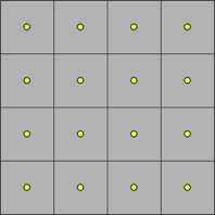
Figure 2 - Squares with yellow dots.
This is classic single sample rasterization. Grey squares represent the pixel square (or a box filter around the pixel center). Yellow dots are the pixel centers at half-integer window coordinate values.

Figure 3 - Squares with yellow dots, halved.
The section line represents a half-space of a primitive. Above and to the left the associated data myMixer is positive. Below and to the right it is negative.
In classic single sample rasterization an in/out/on classification at each pixel center will produce a fragment for pixel centers that are “in” the primitive. The six fragments in this example that must be produced are in the upper left. Those pixels that are “out” are dimmed, and will not have fragments generated.

Figure 4 - Squares with green dots halved with arrows.
Green dots show where shading will take place for each of the six fragments. The associated data myMixer is evaluated at each pixel center. Note that each of the green dots are above and to the left of the half-space, therefore they are all positive. All of the associated data is interpolated.
While our simple shader uses no derivatives (explicit or implied, such as with mipmapped or anisotropic texture fetches), the arrows represent dFdx (horizontal arrow) and dFdy (vertical arrow). In the interior of the primitive they are quite well defined and regular.
Bottom line: with single sampling, fragments are only generated if the pixel center is classified “in,” fragment data is evaluated at the pixel center, interpolation only happens within the primitive, and shading only takes place within the primitive. All is good and “Correct.” (Almost always. For now we'll ignore inaccuracies in some of the derivatives on pixels along the edge of the half-space.)
So, all is (almost) well with single sample rasterization. What can go wrong with multi-sample rasterization?

Figure 5 - Squares with yellow and blue dots.
This is classic multi-sample rasterization. Grey squares represent the pixel square (or a box filter around the pixel center). Yellow dots are the pixel centers at half-integer window coordinate values. Blue dots are sample locations. In this example, I'm showing a simple rotated two sample implementation. Everything generalizes to more samples.
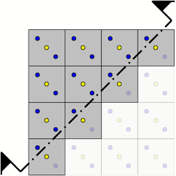
Figure 6 - Squares with yellow and blue dots halved.
The section line again represents a half-space of a primitive. Above and to the left the associated data myMixer is positive. Below and to the right it is negative.
In multi-sample rasterization an in/out/on classification at each sample will produce a fragment if any sample associated with a pixel is “in” the primitive.
The ten fragments in this example that must be produced are in the upper left. (Note the four additional fragments generated along the half-space. One sample is “in” even though the center is “out.”) Those pixels that are “out” are dimmed.

Figure 7 - Squares with yellow blue green and red dots halved.
What if we evaluate at pixel centers?
Green dots and red dots show where shading will take place for each of the ten fragments. The associated data myMixer is evaluated at each pixel center. Note that each of the green dots are above and to the left of the half-space, therefore they are all positive. But also note that each of the red dots are below and to the right of the half-space, therefore they are negative. The green dots are where the associated data is interpolated, red dots are where they are extrapolated.
In the example shader, sqrt(myMixer) is undefined if myMixer is negative. Even though the values written by a vertex shader might be in the range 0.0-1.0, due to the extrapolation that might happen, myMixer can be outside the range 0.0-1.0. When myMixer is negative the result of the fragment shader is undefined!

Figure 8 - Squares with yellow blue green and reds dots halved with arrows.
We're still considering the case of evaluation at pixel centers. While our simple shader uses no derivatives, explicit or implied, the arrows represent dFdx (horizontal arrow) and dFdy (vertical arrow). In the interior of the primitive they are quite well defined because all of the evaluation is at the regular pixel centers.

Figure 9 - Squares with yellow blue and green dots halved with arrows.
What if we evaluate other than at pixel centers?
Green dots show where shading will take place for each of the ten fragments. The associated data myMixer is evaluated at each pixel “centroid.”
The pixel centroid is the center of gravity of the intersection of a pixel square and the interior of the primitive. For a fully covered pixel this is exactly the pixel center. For a partially covered pixel this is often a location other than the pixel center.
OpenGL allows implementers to choose the ideal centroid, or any location that is inside the intersection of the pixel square and the primitive, such as a sample point or a pixel center.
In this example, if the center is “in,” the associated data is evaluated at the center. If the center is “out,” the associated data is evaluated at the sample location that is “in.” Note that for the four pixels along the half-space the associated data is evaluated at the sample.
Also note that each of the green dots are above and to the left of the half-space. Therefore, they are all positive: always interpolated, never extrapolated!
So why not always evaluate at centroid? In general, it is more expensive than evaluating at center. But that's not the most important factor.
While our simple shader uses no derivatives, the arrows represent dFdx (horizontal arrow) and dFdy (vertical arrow). Note that the spacing between evaluations is not regular. They also do not hold y constant for dFdx, or hold x constant for dFdy. Derivatives are less accurate when evaluated at centroid!
Because this is a tradeoff, OpenGL Shading Language Version 1.20 gives the shader writer the choice of when to make the tradeoff with a new qualifier, centroid.
#version 120
centroid varying float myMixer;
// Interpolate color between blue and yellow.
// Let's do a sqrt for a funkier effect.
void main( void )
{
const vec3 blue = vec3( 0.0, 0.0, 1.0 );
const vec3 yellow = vec3( 1.0, 1.0, 0.0 );
float a = sqrt( myMixer ); // undefined when myMixer < 0.0
vec3 color = mix( blue, yellow, a ); // nonlerp
gl_FragColor = vec4( color, 1.0 );
}
When should you consider using centroid?
- When using an extrapolated value could lead to undefined results. Pay particular attention to the built-in functions that say “results are undefined if!”
- When using an extrapolated value with a highly non-linear or discontinuous function. This includes for example specular calculations, particularly when the exponent is large, and step functions.
When should you not consider using centroid?
- When you need accurate derivatives (explicit or implied, such as with mipmapped or anisotropic texture fetches). The shading language specification considers derivatives derived from centroid varings to be so fraught with inaccuracy that it was resolved they are simply undefined. In such a case, strongly consider at least adding:
centroid varying float myMixer; // beware of derivative!
varying float myCenterMixer; // derivative okay - With tessellated meshes where most of the quad or triangle boundaries are interior and well defined anyway. The easiest way to think about this case is if you have a triangle strip of 100 triangles, and only the first and last triangle might result in extrapolations, centroid will make those two triangles interpolate but at the tradeoff of making the other 98 triangles a little less regular and accurate.
- If you know there might be artifacts from undefined, non-linear, or discontinuous functions, but the resulting artifacts are nearly invisible. If the shader is not attacking (much), don't fix it!
Bill Licea-Kane, AMD
Shading Language Technical SubGroup Chair
ARB Next Gen TSG Update
As noted in the previous edition of OpenGL Pipeline, the OpenGL ARB Working Group has divided up the work for defining the API and feature sets for upcoming versions of OpenGL into two technical sub-groups (TSGs): the “Object Model” TSG and the “Next Gen” TSG. While the Object Model group has the charter to redefine existing OpenGL functionality in terms of the new object model (also described in more detail in the last edition), the Next Gen TSG is responsible for developing the OpenGL APIs for a set of hardware features new to modern GPUs.
The Next Gen TSG began meeting weekly in late November and has begun defining this new feature set, code-named “OpenGL Mount Evans.” Several of the features introduced in OpenGL Mount Evans will represent simple extensions to existing functionality such as new texture and render formats, and additions to the OpenGL Shading Language. Other features, however, represent significant new functionality, such as new programmable stages of the traditional OpenGL pipeline and the ability to capture output from the pipeline prior to primitive assembly and rasterization of fragments.
The following section provides a brief summary of the features currently being developed by the Next Gen TSG for inclusion in OpenGL Mount Evans:
- Geometry Shading is a powerful, newly added, programmable stage of the OpenGL pipeline that takes place after vertex shading but prior to rasterization. Geometry shaders, which are defined using essentially the same GLSL as vertex and pixel shaders, operate on post-transformed vertices and have access to information about the current primitive, as well as neighboring vertices. In addition, since geometry shaders can generate new vertices and primitives, they can be used to implement higher-order surfaces and other computational techniques that can benefit from this type of “one-input, many-output” processing model.
- Instanced Rendering provides a mechanism for the application to efficiently render the same set of vertices multiple times but still differentiate each “instance” of rendering with a unique identifier. The vertex shader can read the instance identifier and perform vertex transformations correlated to this particular instance. Typically, this identifier is used to calculate a “per-instance” model-view transformation.
- Integer Pipeline Support has been added to allow full-range integers to flow through the OpenGL pipeline without clamping operations and normalization steps that are based on historical assumptions of normalized floating-point data. New non-normalized integer pixel formats for renderbuffers and textures have also been added, and the GLSL has gained some “integer-aware” operators and built-in functions to allow the shaders to manipulate integer data.
- Texture “Lookup Table” Samplers are specialized types of texture samplers that allow a shader to perform index-based, non-filtered lookups into very large one-dimensional arrays of data, considerably larger than the maximum supportable 1D texture.
- New Uses for Buffer Objects have been defined to allow the application to use buffer objects to store shader uniforms, textures, and the output from vertex and geometry shaders. Storing uniforms in buffer objects allows for efficient switching between different sets of uniforms without repeatedly sending the changed state from the client to the server. Storing textures in a buffer object, when combined with “lookup table” samplers, provides a very efficient means of sampling large data arrays in a shader. Finally, capturing the output from the vertex or geometry shader in a buffer object offers an incredibly powerful mechanism for processing data with the GPU’s programmable execution units without the overhead and complications of rasterization.
- Texture Arrays offer an efficient means of texturing from- and rendering to a collection of image buffers, without incurring large amounts of state-changing overhead to select a particular image from that collection.
While the Next Gen TSG has designated the above items as “must have” features for OpenGL Mount Evans, the following list summarizes features that the group has classified as “nice to have”:
- New Pixel and Texture Formats have been defined to support sRGB color space, shared-exponent and packed floating point, one and two component compression formats, and floating-point depth buffers.
- Improved Blending Support for DrawBuffers would allow the application to specify separate blending state and color write masks for each draw buffer.
- Performance Improvements for glMapBuffer allow the application to more efficiently control the synchronization between OpenGL and the application when mapping buffer objects for access by the host CPU.
The Next Gen TSG has begun work in earnest developing the specifications for the features listed above, and the group has received a tremendous head start with a much-appreciated initial set of extension proposals from NVIDIA. As mentioned, the Next Gen TSG is developing the OpenGL Mount Evans features to fit into the new object model introduced by OpenGL Longs Peak. Because of these dependencies, the Next Gen TSG has the tentative goal of finishing the Mount Evans feature set specification about 2-3 months after the Object Model TSG completes its work defining Longs Peak.
Please check back in the next edition of "OpenGL Pipeline" for another status update on the work being done in the Next Gen TSG.
Jeremy Sandmel, Apple
Next Gen Technical SubGroup Chair
Using the Longs Peak Object Model
In OpenGL Pipeline #002, Barthold Lichtenbelt gave the high-level design goals and structure of the new object model being introduced in OpenGL Longs Peak. In this issue we'll assume you're familiar with that article and proceed to give some examples using the actual API, which has mostly stabilized. (We're not promising the final Longs Peak API will look exactly like this, but it should be very close.)
Template and Objects
In traditional OpenGL, objects were created, and their parameters (or “attributes,” in our new terminology) set after creation. Calls like glTexImage2D set many attributes simultaneously, while object-specific calls like glTexParameteri set individual attributes.
In the new object model, many types of objects are immutable (can't be modified), so their attributes must be defined at creation time. We don't know what types of objects will be added to OpenGL in the future, but do know that vendor and ARB extensions are likely to extend the attributes of existing types of objects. Both reasons cause us to want object creation to be flexible and generic, which led to the concept of “attribute objects,” or templates.
A template is a client-side object which contains exactly the attributes required to define a “real” object in the GL server. Each type of object (buffers, images, programs, shaders, syncs, vertex arrays, and so on) has a corresponding template. When a template is created, it contains default attributes for that type of object. Attribute values in templates can be changed.
Creating a “real” object in the GL server is done by passing a template to a creation function, which returns a handle to the new object. In order to avoid pipeline stalls, object creation does not force a round-trip to the server. Instead, the client speculatively returns a handle which may be used in future API calls. (If creation fails, future use of that handle will generate a new error, GL_INVALID_OBJECT.)
Example: Creating an Image Object
In Longs Peak, we are unifying the concepts of “images” -- such as textures, pixel data, and render buffers -- and generic “buffers” such as vertex array buffers. An image object is a type (“subclass,” in OOP terminology) of buffer object that adds additional attributes such as format and dimensionality. Here's an example of creating a simple 2D image object. This is not intended to show every aspect of buffer objects, just to show the overall API. For example, the format parameter below is assumed to refer to a GLformat object describing the internal format of an image.
// Create an image template
GLtemplate template = glCreateTemplate(GL_IMAGE_OBJECT);
assert(template != GL_NULL_OBJECT);
// Define image attributes for a 256x256 2D texture image
// with specified internal format
glTemplateAttribt_o(template, GL_FORMAT, format);
glTemplateAttribt_i(template, GL_WIDTH, 256);
glTemplateAttribt_i(template, GL_HEIGHT, 256);
glTemplateAttribt_i(template, GL_TEXTURE, GL_TRUE);
// Create the texture image object
GLbuffer image = glCreateImage(template);
// Define the contents of the texture image
glImageData2D(image,
0, // mipmap level 0
0, 0, // copy at offset (0,0) within the image
256, 256, // copy width and height 256 texels
GL_RGBA, GL_UNSIGNED_BYTE, // format & type of <data>
data); // and the actual texels to use
Once image has been created and its contents defined, it can be attached (along with a texture filter object) to a program object, for use by shaders. The contents of the texture, or any rectangular subregion of it, can be changed at any time using glImageData2D.
API Design Concerns
You may have some concerns when looking at this example. In particular, it doesn't look very object-oriented, and it appears verbose compared to the classic glGenTextures() / glBindTexture() / glTexImage2D() mechanism.
While we do have an object-oriented design underlying Longs Peak, we still have to specify it in a traditional C API. This is mostly because OpenGL is designed as a low-level, cross-platform driver interface, and drivers are rarely written in OO languages; nor do we want to lock ourselves down to any specific OO language. We expect more compact language bindings will quickly emerge for C++, C#, Java, and other object-oriented languages, just as they have for traditional OpenGL. But with the new object model design, it will be easier to create bindings which map naturally between the language semantics and the driver behavior.
Regarding verbosity, the new object model gains us a consistent set of design principles and APIs for manipulating objects. It precisely defines behaviors such as object sharing across contexts and object lifetimes, which are sometimes open to interpretation in traditional OpenGL. And it makes defining new object types in the future very easy. But the genericity of the APIs, in particular those required to set the many types of attributes in a template, may look a bit confusing and bloated at first. Consider
glTemplateAttribt_i(template, GL_WIDTH, 256);
First, why the naming scheme? What does t_i mean? Each attribute in a template has a name by which it's identified, and a value. Both the name and the value may be of multiple types. This example is among the simplest: the attribute name is GL_WIDTH (an enumerated token), and the value is a single integer.
The naming convention we're using is glTemplateAttrib<name type>_<value type>. Here, t means the type is an enumerated token, and i means GLint, as always. The attribute name and value are specified consecutively in the parameter list. Using these conventions we can define many other attribute-setting entry points. For example:
glTemplateAttribt_fv - name is a token, value is an array of GLfloat (fv).
glTemplateAttribti_o - name is a (token,index) tuple, value is an object handle. This might be used in specifying attachments of buffer objects to new-style vertex array objects, for example, where many different buffers can be attached, each corresponding to an indexed attribute.
Object Creation Wrappers
Great, you say, but all that code just to create a texture? There are two saving graces.
First, templates are reusable - you can create an object using a template, then change one or two of the attributes in the template and create another object. So when creating a lot of similar objects, there needn't be lots of templates littering the application.
Second, it's easy to create wrapper functions which look more like traditional OpenGL, so long as you only need to change a particular subset of the attributes using the wrapper. For example, you could have a function which looks a lot like glTexImage2D:
GLbuffer gluCreateTexBuffer2D(GLint miplevel, GLint internalformat,
GLsizei width, GLsizei height, GLenum format, GLenum type,
const GLvoid *pixels)
This function would create a format object from internalformat; create an image template from the format object, width, height, and miplevel (which defaulted to 0 in the original example); create an image object from the template; load the image object using format, type, and pixels; and return a handle to the image object.
We expect to provide some of these wrappers in a new GLU-like utility library - but there is nothing special about such code, and apps can write their own based on their usage patterns.
Any “Object”ions?
We've only had space to do a bare introduction to using the new object model, but have described the basic creation and usage concepts as seen from the developer's point of view. In future issues, we'll delve more deeply into the object hierarchy, semantics of the new object model (including sharing objects across contexts), additional object types, and how everything goes together to assemble the geometry, attributes, buffers, programs, and other objects necessary for drawing.
Jon Leech
OpenGL Spec Editor
A First Glimpse at the OpenGL SDK
By the time you see this article, the new SDK mentioned in the Autumn edition of OpenGL Pipeline will be public. I will not hide my intentions under layers of pretense; my goal here is to entice you to go check it out. I will try to be subtle.

The SDK is divided into categories. Drop-down menus allow you to navigate directly to individual resources, or you can click on a category heading to visit a page with a more detailed index of what's in there.

The reference pages alone make the SDK a place you'll keep coming back to. If you're like me, reaching for the "blue book" is second nature any time you have a question about an OpenGL command. These same pages can be found in the SDK, only we've taken them beyond OpenGL 1.4. They're now fully updated to reflect the OpenGL 2.1 API! No tree killing, no heavy lifting, just a few clicks to get your answers.

The selection of 3rd-party contributions is slowly growing with a handful of libraries, tools, and tutorials. Surf around (http://www.opengl.org/sdk), and be sure to check back often. We're just getting started!
Benj Lipchak, AMD
Ecosystem Technical SubGroup Chair
Polygons In Your Pocket: Introducing OpenGL ES
If you're a regular reader of OpenGL Pipeline, you probably know that you can use OpenGL on Macs, PCs (under Windows or Linux), and many other platforms ranging from workstations to supercomputers. But, did you know that you can also use it on PDAs and cell phones? Yes, really!
Okay, not really, at least not yet; but you can use its smaller sibling, OpenGL ES. OpenGL ES is OpenGL for Embedded Systems, including cell phones in particular, but also PDAs, automotive entertainment centers, portable media players, set-top boxes, and -- who knows -- maybe, someday, wrist watches and Coke® machines.
OpenGL ES is defined by the Khronos Group, a consortium of cell phone manufacturers, silicon vendors, content providers, and graphics companies. Work on the standard began in 2002, with support and encouragement from SGI and the OpenGL ARB. The Khronos Group's mission is to enable high-quality graphics and media on both mobile and desktop platforms. In addition to OpenGL ES, Khronos has defined standards for high-quality vector graphics, audio, streaming media, and graphics asset interchange. In 2006, the OpenGL ARB itself became a Khronos working group, and many ARB members are active in OpenGL ES discussions.
Why OpenGL ES?
When the Khronos group began looking for a mobile 3D API, the advantages of OpenGL were obvious: it is powerful, flexible, non-proprietary, and portable to many different OSes and environments. However, just as human evolution left us with tailbones and appendices, OpenGL's evolution has left it with some features whose usefulness for mobile applications is, shall we say, non-obvious: color index mode, stippling, and GL_POLYGON_SMOOTH antialiasing, to name a few. In addition, OpenGL often provides several ways to accomplish the same basic goal, and it has some features that have highly specialized uses and/or are expensive to implement. The Khronos OpenGL ES Working Group saw this as an opportunity: by eliminating legacy features, redundant ways of doing things, and features not appropriate for mobile platforms, they could produce an API that provides most of the power of desktop OpenGL in a much smaller package.
Design Guidelines
The Khronos OpenGL ES Working Group based its decisions about which OpenGL features to keep on a few simple guidelines:
If in doubt, leave it out
Rather than starting with desktop OpenGL and deciding what features to remove, start with a blank piece of paper and decide what features to include, and include only those features you really need.
Eliminate redundancy
If OpenGL provides multiple ways of doing something, include at most one of them. If in doubt, choose the most efficient.
"When was the last time you used this?"
If in doubt about whether to include a particular feature, look for examples of recent applications that use it. If you can't find one, you probably don't need it.
The Principle of Least Astonishment
Try not to surprise the experienced OpenGL programmer; when importing features from OpenGL, don't change anything you don't have to. OpenGL ES 1.0 is defined relative to desktop OpenGL 1.3 – the specification is just a list of what is different, and why. Similarly, OpenGL ES 1.1 is defined as a set of differences from OpenGL 1.5.
OpenGL ES is almost a pure subset of desktop OpenGL. However, it has a few features that were added to accommodate the limitations of mobile devices. Handhelds have limited memory, so OpenGL ES allows you to specify vertex coordinates using bytes as well as the usual short, int, and float. Many handhelds have little or no support for floating point arithmetic, so OpenGL ES adds support for fixed point. For really light-weight platforms, OpenGL ES 1.0 and 1.1 define a "light" profile that doesn't use floating point at all.
To Market
OpenGL ES has rapidly replaced proprietary 3D APIs on mobile phones, and is making rapid headway on other platforms. The original version 1.0 is supported in Qualcomm's BREW® environment for cell phones, and (with many extensions) on the PLAYSTATION®3. The current version (ES 1.1) is supported on a wide variety of mobile platforms.
Learning More
In future issues of OpenGL Pipeline, I'll go into more detail about the various OpenGL ES versions and how they differ from their OpenGL counterparts. But for the real scoop, you'll need to look at the specs. As I said earlier, the current OpenGL ES specifications refer to a parent desktop OpenGL spec, listing the differences between the ES version and the parent. This is great if you know the desktop spec well, but it's confusing for the casual reader. For those who prefer a self-contained document, the working group is about to release a stand-alone version of the ES 1.1 specification, and (hurray!) man pages. You can find the current specifications and (soon) other documentation at http://www.khronos.org/opengles/1_X/.
Take It for a Test Drive
OpenGL ES development environments aren't quite as easy to find as OpenGL environments, but if you want to experiment with it, you have several no-cost options. The current list is at http://www.khronos.org/developers/resources/opengles. Many of these toolkits and SDKs target multiple mobile programming environments, and many also offer the option of running on Windows, Linux, or both. There's also an excellent open source implementation, Vincent.
Watch This Space
Since releasing OpenGL ES 1.1 in 2004, the Working Group has been busier than ever. Later this year we'll release OpenGL ES 2.0, which (you guessed it) is based on OpenGL 2.0, and brings modern shader-based graphics to handheld devices. You can expect to see ES 2.0 toolkits later this year, and ES2-capable devices in 2008 and 2009. Also under development or discussion are the aforementioned stand-alone specifications and man pages, educational materials, an effects framework, and (eventually) a mobile version of Longs Peak.
I hope you've enjoyed this quick overview of OpenGL ES. We'd love to have your feedback! Look for us at conferences like SIGGRAPH and GDC, or visit the relevant discussion boards at http://www.khronos.org.
Tom Olson, Texas Instruments, Inc.
OpenGL ES Working Group Chair
Climbing OpenGL Longs Peak – An OpenGL ARB Progress Update
Longs Peak – 14,255 feet, 15th highest mountain in Colorado. Mount Evans is the 14th highest mountain in Colorado. (Therefore, we have at least 13 OpenGL revisions to go!)
As you might know, the ARB is planning a lot for 2007. We're hard at work on not one, but two, OpenGL specification revisions code named "OpenGL Longs Peak" and "OpenGL Mount Evans." If you're not familiar with these names, please look at the last edition of the OpenGL Pipeline for an overview. Besides two OpenGL revisions and conformance tests for these, the ARB is also working on an OpenGL SDK, which I am very excited about. This SDK should become a valuable resource for you, our developer community. You can find more about the SDK in the Ecosystem TSG update in this issue.
OpenGL Longs Peak will bring a new object model, which was described in some detail in the last OpenGL Pipeline. Since that last update, we made some important decisions that I would like to mention here:
- Object creation is asynchronous. This means that the call you make to create an object can return to the caller before the object is actually created by the OpenGL implementation. When it returns to the caller, it returns a handle to this still to be created object. The cool thing is that this handle is a valid handle; you can use it immediately if needed. What this provides is the ability for the application and the OpenGL implementation to overlap work, increasing parallelism which is a good thing. For example, consider an application that knows it needs to use a new texture object for the next character it will render on the screen. During the rendering of the current character the application issues a create texture object call, stores away the handle to the texture object, and continues issuing rendering commands to finish the current character. By the time the application is ready to render the next character, the OpenGL implementation has created the texture object, and there is no delay in rendering.
- Multiple program objects can be bound. In OpenGL 2.1 only one program object can be in use (bound) for rendering. If the application wants to replace both the vertex and fragment stage of the rendering pipeline with its own shaders, it needs to incorporate all shaders in that single program object. This is a fine model when there are only two programmable stages, but it starts to break down when the number of programmable stages increases because the number of possible combinations of stages, and therefore the number of program objects, increases. In OpenGL Longs Peak it will be possible to bind multiple program objects to be used for rendering. Each program object can contain only the shaders that make up a single programmable stage; either the vertex, geometry or fragment stage. However, it is still possible to create a program object that contains the shaders for more than one programmable stage.
- The distinction between unformatted/transparent buffer objects and formatted/opaque texture objects begins to blur. OpenGL Longs peak introduces the notion of image buffers. An image buffer holds the data part (texels) of a texture. (A filter object holds the state describing how to operate on the image object, such as filter mode, wrap modes, etc.) An image buffer is nothing more than a buffer object, which we all know from OpenGL 2.1, coupled with a format to describe the data. In other words, an image object is a formatted buffer object and is treated as a subclass of buffer objects.
- A shader writer can group a set of uniform variables into a common block. The storage for the uniform variables in a common block is provided by a buffer object. The application will have to bind a buffer object to the program object to provide that storage. This provides several benefits. First, the available uniform storage will be greatly increased. Second, it provides a method to swap sets of uniforms with one API call. Third, it allows for sharing of uniform values among multiple program objects by binding the same buffer object to different program objects, each with the same common block definition. This is also referred to as "environment uniforms," something that in OpenGL 2.1 and GLSL 1.20 is only possible by loading values into built-in state variables such as the gl_ModelViewMatrix.
We are currently debating how we want to provide interoperability between OpenGL 2.1 and OpenGL Longs Peak. Our latest thinking on this is as follows. There will be a new context creation call to indicate if you want an OpenGL 2.1 context or an OpenGL Longs Peak context. An application can create both types of contexts if desired. Both OpenGL 2.1 and Longs Peak contexts can be made current to the same drawable. This is a key feature, and allows an application that has an OpenGL 2.1 (or earlier) rendering pipeline to open a Longs Peak context, use that context to draw an effect only possible with Longs Peak, but render it into the same drawable as its other context(s). To further aid in this, there will be an extension to OpenGL 2.1 that lets an application attach an image object from a Longs Peak context to a texture object created in an OpenGL 2.1 context. This image object becomes the storage for the texture object. The texture object can be attached to a FBO in the OpenGL 2.1 context, which in turn means an OpenGL 2.1 context can render into a Longs Peak image object. We would like your feedback on this. Is this a reasonable path forward for your existing applications?
The work on OpenGL Mount Evans has also started in earnest. The Next Gen TSG is meeting on a weekly basis to define what this API is going to look like. OpenGL Mount Evans will also bring a host of new features to the OpenGL Shading Language, which keeps the Shading Language TSG extremely busy. You can find more in the Next Gen update article in this issue.
Another area the ARB is working on is conformance tests for OpenGL Longs Peak and Mount Evans. We will be updating the existing set of conformance tests to cover the OpenGL Shading Language and the OpenGL Longs Peak API. Conformance tests ensure a certain level of uniformity among OpenGL implementations, which is a real benefit to developers seeking a write-once, run anywhere experience. Apple is driving the definition of the new conformance tests.
Lastly, a few updates on upcoming trade shows. We will be at the Game Developers Conference in San Francisco on Wednesday March 7, presenting in more detail on OpenGL Longs Peak and other topics. Watch opengl.org for more information on this! As usual we will be organizing a BOF (Birds of a Feather) at SIGGRAPH, which is in San Diego this year. We have requested our usual slot on Wednesday August 8th from 6-8pm, but it has not yet been confirmed. Again, watch opengl.org for an announcement. Hopefully I'll meet you at one of these events!
In the remainder of this issue you'll find an introduction to OpenGL ES, updates from various ARB Technical SubGroups, timely information about OpenGL on Microsoft Vista, and an article covering how-to optimize your OpenGL application using gDEBugger. We will continue to provide quarterly updates of what to expect in OpenGL and of our progress so far.
Barthold Lichtenbelt, NVIDIA
Khronos OpenGL ARB Steering Group chair
“Clean” your OpenGL usage using gDEBugger
Cleaning up your application's OpenGL usage is the first step to optimize your application and gain better performance. In this article we will demonstrate how gDEBugger helps you verify that your application uses OpenGL correctly and calls the OpenGL API commands you expect it to call.
Remove OpenGL Errors
Removing OpenGL errors before starting to optimize your graphics application's performance is an important task. It is important because in most cases, when an OpenGL error occurs, OpenGL ignores the API call that generated the error. If OpenGL ignores actions that you want it to perform, it may reduce your application's robustness and dramatically affect rendering performance. The OpenGL error mechanism does not tell you the location of the error and therefore it is hard to track GL errors. gDEBugger points you to the exact location of the OpenGL error. It offers two mechanisms for tracking errors:
 Break on OpenGL Errors: Breaks the application run whenever an OpenGL error occurs.
- Break on Detected Errors: Tells gDEBugger's OpenGL implementation to perform additional error tests that OpenGL drivers do not perform. gDEBugger will also break the application run whenever a detected error occurs.
After the application run is suspended, the gDEBugger System Events view will display the error description. The Call Stack and Source Code viewers will show you the exact location of the error.
Remove Redundant OpenGL Calls
Most OpenGL-based applications generate a lot of redundant OpenGL API calls. Some of these redundant calls may have a significant impact on rendering performance. We offer a two-step solution for locating and removing these redundant calls:
- Use gDEBugger's OpenGL Function Calls Statistics view to get an overview of the last fully rendered frame. This view displays the number of times each API function call was executed in the previously fully rendered frame. You should look for:
- functions that have a high percentage of the total API function executions.
- functions that are known to reduce rendering performance: glGet* / glIs* functions, immediate mode rendering, glFinish, etc.
- redundant OpenGL state changes: changing the same state over and over.
- repeatedly turning on and off the same OpenGL mechanisms.
 Use the Breakpoints dialog to break on each redundant API function call. When the application run breaks, use the OpenGL Function Calls History, Call Stack and Source Code views to view the call stack and source code that led to the redundant API call
This process should be repeated until the redundant calls that seem to have impact on rendering performance are removed.
Locate Software Fallbacks
When the application calls an OpenGL function or establishes a combination of OpenGL state that is not accelerated by the graphics hardware (GPU), the driver runs these functions on the CPU in "software mode." This causes a significant decrease in rendering performance. gDEBugger and NVIDIA GLExpert driver integration offers a mechanism that traces software fallbacks. Simply check the "Report Software Fallback Messages" and "Break on GLExpert Reports" check boxes in gDEBugger's NVIDIA GLExpert Settings dialog. In this mode, whenever a "Software Fallback" occurs, gDEBugger will break the debugged application run, letting you view the call stack and source code that led to the software fallback.
We hope this article will help you deliver "cleaner" and faster OpenGL based applications. In the next article we will discuss the use of ATI and NVIDIA Performance Counters together with gDEBugger's Performance Views for finding graphics pipeline performance bottlenecks.
Yaki Tebeka
CTO & Cofounder
Graphic Remedy
Editors Note: You'll remember from our last edition that Graphic Remedy and the ARB have teamed up to make gDEBugger available free to non-commercial users for a limited time.
Platform TSG Update
The Platform TSG is one of the more specialized subgroups within the new ARB. Our charter is, broadly, to deal with issues specific to the various platforms on which OpenGL is implemented. In practice this means we're responsible for the GLX and WGL APIs that support OpenGL drivers running within the platform native window system, as well as being the liaison to EGL, which is specified by the OpenKODE Graphics TSG within Khronos.
We also will look at general OS and driver integration issues such as platform ABIs and Device Driver Interfaces, reference libraries, and so on, although much of this work may be performed primarily outside Khronos. For example, the Linux ABI is being updated within the Linux Standards Base project, although Khronos members are significant contributors to that work.
Currently, we are finishing up GLX protocol to support vertex buffer objects, based on work Ian Romanick of IBM has been doing within Mesa. This will lead to an updated GLX Protocol specification in the relatively near future.
Jon Leech
Platform TSG Interim Chair
The New Object Model
The Object Model TSG has been working diligently on the new object model. Object management in OpenGL is changing considerably. There will soon be a consistent way to create, edit, share and use objects.
The existing object model evolved over time, and did not have a consistent design. It started with display lists in OpenGL 1.0, and then added texture objects in OpenGL 1.1. Unfortunately texture objects were added in a less than optimal way. The combination of glBindTexture and glActiveTexture makes it hard to follow and debug code, for example. Texture objects can be incomplete, and worse, their format and size can be redefined with a call to glTexImage1D/2D/3D. After texture objects, new object types were added with sometimes inconsistent semantics. Furthermore, the existing object model is optimized for object creation, not for runtime performance. Most applications create objects once, but use them often. It makes more sense to ensure that using an object for rendering is lightweight. This is not the case right now.
The goals we are shooting for with the new object model are to:
- achieve maximum runtime performance
- eliminate incomplete objects
- allow for sharing across contexts on a per-object basis
- (partially) eliminate existing bind semantics
I'll explain each of these goals in the following paragraphs.
Maximum runtime performance is influenced by many factors, including the application's ability to use the underlying hardware as efficiently as possible. In the context of the new object model it means that maximum runtime performance is achieved only when overhead in the OpenGL driver is minimized. The new object model reduces driver overhead in several ways:
- The amount of validation the OpenGL implementation needs to perform at draw time will be reduced. In OpenGL today, quite a lot of validation can and will happen at draw time, slowing rendering down.
- Fewer state changes will be needed in the new object model, again improving runtime performance. For example, the number of bind operations, or copies of uniform values, will be reduced.
- The new object model will reduce time spent in the OpenGL driver looking up object handles.
The fact that incomplete objects can exist adds flexibility to OpenGL, but without a clear benefit. They make it harder for the OpenGL implementation to intelligently allocate memory for objects, can result in more validation at rendering time, and can leave developers confused when rendering does not produce expected results. For example, a texture object is built up one mipmap level at a time. The OpenGL implementation has no idea in advance what the total memory requirements will be when an application hands it the first mipmap level. And if the application fails to provide a complete set of mipmap levels when mipmapping is enabled, that incomplete texture will not be used at all while rendering, a pitfall that can be difficult to debug.
Sharing of objects across contexts is an "all or nothing" switch today. Dangerous race conditions can occur when one context is using an object while another context is changing the object's size, for example. Not to mention what happens when deleting an object in one context while it is still in use in another context. This case actually leads to different behavior on different implementations due to ambiguities in the existing spec language.
The existing object model's "bind to edit" and "bind to use" semantics can have complex side effects and in general are confusing. There is no good reason to bind an object into the current rendering state if it just needs to be edited. Binding should only occur when the object is required for rendering.
The new object model is designed to overcome the flaws of the old one. Here are some of the highlights:
- Object creation is atomic. All attributes needed to create an object are passed at creation time. Once created, the OpenGL implementation returns a handle to the new object.
- An object handle is passed as a parameter to an OpenGL command in order to operate on the object. Gone is the bind semantic just to edit an object. Binding is only required when using an object for rendering.
- An attribute can be set at object creation time to indicate if the object is eligible to be shared across contexts. Creation will fail if that type of object cannot be shared. Container objects, such as FBOs, cannot be shared across contexts in order to eliminate associated race-conditions. Container objects are light-weight, so duplicating one in another context is not a great burden.
- All attributes passed at object creation time are immutable. This means that those properties of an object cannot be subsequently changed. Instead, a new object would be created by the application with a different set of attributes. For example, an image object needs to have its size and dimensionality set at creation time. Once created, it is no longer possible to change the size of an image object. The data stored in the image object is, however, mutable. Compare this to the old object model where both the size and data of a texture object are mutable. A call to glTexImage will both resize the texture object and replace the texel data in the object. Separating the object's shape and size from its data in this way has some nice side effects. It removes guesswork by the OpenGL implementation about what the object will look like, so it can make intelligent choices up front about memory allocation. It makes for more efficient sharing across contexts, since it removes dangerous race-conditions with respect to the shape and size.
- It is more efficient for the OpenGL implementation to validate an object at render time, which in turn means higher rendering performance.
- The new object model is easier for OpenGL application developers to use.
- There will be new data types in the form of a per-object class typedef, which will enforce strong type-checking at compile time. This should be a nice aid, and if a compiler warning or error occurs, an early indicator of coding issues.
- An object handle will be the size of the pointer type on the system the OpenGL implementation is running. This allows, but does not mandate, the OpenGL implementation to store a pointer to an internal data structure in the handle. This in turn means that the OpenGL implementation can very quickly resolve a handle being passed, resulting in higher performance. Of course, this can also lead to possible crashes of the application. A debug layer can help find these kind of bugs during development of a title.
- The new object model is intended to be easier for OpenGL application developers to use.
Stay tuned to opengl.org for more information! We have most object types worked out now, and are in the process of writing all this up in spec form. Once all object types have been worked out, we'll run it by you, our developer community.
Barthold Lichtenbelt, NVIDIA
Object Model TSG Chair
One SDK to Rule Them All
The Ecosystem TSG has been focused on one goal this past quarter: delivering an OpenGL SDK. We intend the SDK to serve as one-stop-shopping for the tools and reference materials that developers desire, nay, demand in order to effectively and efficiently target the OpenGL API. In an opengl.org poll conducted earlier this year, you let us know in no uncertain terms that above all else you'd like to see the ARB publish a full-blown SDK. Herein I will describe the various components we're planning to include.
- Documentation
- We will provide reference documentation for all OpenGL 2.1 core entrypoints. We aim to make this available in a variety of convenient formats, including HTML and PDF. Over time we may also back-fill this reference material to cover ARB extensions.
Aside from the relatively dry reference docs, we'll also feature a number of tutorials which will walk you through the use of OpenGL API features, from your very first basic OpenGL program to the latest and greatest advanced rendering techniques. These tutorials will be contributed by the most respected OpenGL tutorial sites on the web.
- We will provide reference documentation for all OpenGL 2.1 core entrypoints. We aim to make this available in a variety of convenient formats, including HTML and PDF. Over time we may also back-fill this reference material to cover ARB extensions.
- Samples
- What better way to start your own OpenGL project than by reusing someone else's sample code? And what better way to spark your imagination and see what's possible with OpenGL than by running cutting-edge demos on your own system? This category will contain both samples (with source code), and demos (without source).
- Libraries
- No need to reinvent the wheel. Others have already abstracted away window system specific issues, initialization of extension entrypoints, loading of images, etc. Make use of the libraries in this category and spend your development time on the exciting new things you're bringing to life with OpenGL.
- Tools
- There are some impressive tools and utilities out there to make your life easier while developing for OpenGL. Whether you need a debugger, a performance profiler, or just an image compressor, we'll have you covered in this category of the SDK. Some of these tools are commercially available, while others are free.
- Conformance tests
- The success of OpenGL depends on all implementations behaving the same way. When you write an application on one piece of hardware, you want it to run smoothly on others. This requires the graphics drivers from various vendors to all conform to a single set of rules: the OpenGL specification (which of course is also available as part of the SDK). A suite of tests will be developed to help ensure that compatibility can be maintained and developers won't spend the majority of their precious time writing vendor-specific code paths to work around incompatibilities.
Does it seem like the ARB is biting off more than it can chew? Absolutely. That's why we're teaming with leading OpenGL companies, open source projects, and individual professionals who will do all the heavy lifting. The SDK will be a clearinghouse for contributions in the above categories which the Ecosystem TSG has deemed worthy of your attention. The ARB will still be on the hook for reference documentation, conformance tests, and other components that we're in a unique position to supply. But wherever possible we'll be leaning on the rest of the community to step up to the plate and help flesh out our SDK -- your SDK.
Benj Lipchak, AMD
Ecosystem TSG Chair
Transitions
As of September 21st, 2006, the OpenGL Architecture Review Board (the ARB) has ceased to exist. As described in the previous issue of OpenGL Pipeline, OpenGL API standardization has moved to Khronos, and will take place in the new OpenGL ARB Working Group (WG). We've retained the ARB label as a historical nod, so it makes sense to continue using the "ARB" suffix in extensions the group approves.
After holding the job for nine years, Jon Leech decided to step down as the ARB secretary. Barthold Lichtenbelt has been elected unanimously to lead the ARB. A big thank you to Jon for a job well done!
In general, the ARB WG will operate very much like the old, independent ARB. One great advantage of joining Khronos is closer collaboration with our sister working group, the OpenGL ES working group. This working group develops an API based on OpenGL and the OpenGL Shading Language for the handheld and embedded markets. Before joining Khronos, swapping ideas with the OpenGL ES group was difficult, mainly due to IP concerns. That barrier is now gone. Another huge benefit to joining Khronos is the extra support the ARB gets in the form of professional marketing and clout that comes with being associated with the Khronos name. Procedurally, not much changes. The Khronos bylaws and procedures differ in minor ways; the only major change is a final review and signoff performed by the Khronos Board of Promoters on any specifications the ARB WG develops.
The main task for the ARB is to deliver two new OpenGL releases in 2007. The first one, code named OpenGL "Longs Peak" (the actual releases will have version numbers), is slated to be released in summer 2007. The second one, code named OpenGL "Mt. Evans", is targeted for an October 2007 release. Why code names? We want to give the ARB's marketing group a chance to think through what the right names would be for these releases. Too many suggestions have already been made, including OpenGL 2.2, OpenGL 3.0, OpenGL 3.1 and even OpenGL 4.0. This is not the time yet to pin down the version number, and therefore we'll be using code names.
OpenGL Longs Peak will be a significant departure for us. While there will still be backwards API compatibility, the new "Lean and Mean" profile, and a substantial refactoring in terms of the new object model, make it in many ways an entirely new API design. This is an ambitious task and requires a high degree of commitment from the ARB members. We are already seeing some welcome participation from Khronos members who were not members of the old ARB, and hope to see much more.
While OpenGL Longs Peak will be implementable on current and last generation hardware, OpenGL Mt. Evans will only be implementable on the newest hardware available. The OpenGL Mt. Evans release will be a continuation of OpenGL Longs Peak, with a lot of new functionality added. Some of the highlights are: geometry shading, a more central role for buffer objects, and a full integer pipeline accessible via the OpenGL Shading Language.
Why two new OpenGL releases do you ask? This split in two makes it easy for ISVs to develop a new title spanning a wide range of graphics hardware. By coding their core rendering engine to OpenGL Longs Peak, both older and the newest hardware will be covered. By then coding incrementally to the OpenGL Mt. Evans API, the newest hardware can be exploited to its maximum potential.
Lastly, here is more detail about the ARB Working Group organizational structure. The ARB WG contains a top-level Steering Group (SG) and a number of "Technical Sub-Groups" or TSGs. Each TSG focuses on a specific area and has its own chairman. At present, the responsibilities and structure of the ARB WG include:
- OpenGL ARB Steering Group (Chair: Barthold Lichtenbelt, NVIDIA)
- The top-level SG will define the overall OpenGL strategy and timeline; liaise with the OpenGL ES Working Group; develop conformance tests; and perform any other major functions not assigned to one of the TSGs.
- Ecosystem TSG (Chair: Benj Lipchak, AMD)
- The Ecosystem TSG will develop the OpenGL SDK, in cooperation with many external projects and developers who are contributing to this effort; write developer documentation; develop naming conventions; define the partitioning between the core OpenGL Longs Peak "Lean and Mean" profile and the compatibility layer for OpenGL 1.x/2.x; support outside efforts such as the subsidy program for academic users of Graphic Remedy's gDEBugger; and perform some marketing functions, such as this OpenGL Pipeline newsletter.
- Object Model TSG (Chair: Barthold Lichtenbelt, NVIDIA)
- The Object Model TSG will define the new object model; figure out how existing OpenGL functionality such as framebuffer objects, program objects, texture objects, etc. will be expressed in the new model; and define small bits of entirely new functionality such as sync objects. This is where most of the work for OpenGL Longs Peak will take place.
- Platform TSG (Chair: Jon Leech)
- The Platform TSG will define the GLX and WGL APIs and GLX stream protocol; liaise with the Khronos OpenKODE Steering Group to provide requirements for the EGL API (a platform-neutral analog of GLX and WGL); and handle topics related to OS integration such as Application Binary Interfaces, Device Driver Interfaces, or reference source code for link libraries and shim layers.
- Shading Language TSG (Chair: Bill Licea-Kane, AMD)
- The Shading Language TSG will be responsible for all aspects of the OpenGL Shading Language, including new functionality needed in both the Longs Peak and Mt. Evans releases. This TSG will also liaise with OpenGL ES Shading Language work taking place in the Khronos OpenGL ES Working Group.
- Next Gen TSG (Chair: Jeremy Sandmel, Apple)
- The Next Gen TSG will be responsible for all aspects of the Mt. Evans API design, keeping the new functionality aligned with the new object model being designed by the Object Model TSG.
In the remainder of this issue, there's more information about OpenGL Longs Peak and Mt. Evans, and about activity happening in some of the TSGs. We will continue to provide quarterly updates of what to expect in OpenGL and of our progress so far. But for now it's back to the teleconference salt mines. We have a very aggressive schedule to meet and don't want to disappoint!
Jon Leech
OpenGL ARB Secretary, outgoing
Barthold Lichtenbelt, NVIDIA
Khronos OpenGL ARB Steering Group Chair, incoming
Improved synchronization across GPUs and CPUs - No more glFinish!
The Async Working Group recently finished the ARB_sync specification. It provides a synchronization model that enables a CPU to synchronize with a GPU OpenGL command stream across multiple OpenGL contexts and multiple CPU threads. This extension, for example, allows you to find out if OpenGL has finished processing a GL command without calling glFinish. As you know, glFinish
is a heavyweight operation that you really should not call more than once per frame. Calling it is so expensive because it drains all commands that OpenGL has buffered up before resuming processing.
This extension also allows you, for example, to synchronize rendering in one context with rendering in another context without calling
glFinish. Say you are rendering to a texture in one context while another context needs to use the result of that rendering. You do this by inserting a fence right after the rendering to texture commands in the one context and waiting for the fence to complete in the other context. Again, there is no need to call glFinish!
A link to the actual extension and a discussion are here: http://www.opengl.org/discussion_boards/ubb/ultimatebb.php?ubb=get_topic;f=3;t=014377 Please let us know how you would use this extension, what you think is good about it, and what needs some work.
Currently the Async Working Group is transforming this extension into the new object model that the superbuffers Working Group is working on. We are also starting to look at extending the ARB_sync extension to provide synchronization with, for example, each vertical retrace (vblank) and adding the capability to figure out at what time exactly a fence completed. Another topic on our agenda is to look at so-called ‘predicated rendering.’ Think of this as an occlusion query test, where the result of the test automatically controls whether a set of geometry is rendered by the GPU, without any CPU intervention.
Barthold Lichtenbelt, NVIDIA
Async Working Group Chair
New Texture Functions with Awkward Names to Avoid Ugly Artifacts
One problem with many of the extension specs that we face is that they are too often short on motivating examples. Even when there are examples, they suffer from dreaded ASCII art. With this newsletter, I can not only put in a few more examples, I can replace the dreaded ASCII art with the less dreaded programmer art.
Note, these example procedural shaders will alias. And since they will alias, why not use an aliased source texture as well?
Figure 1 – Source texture – aliasing yellow and blue stripes!
So let’s start with a trivial shader: apply this texture to a quad. The quad has texture coordinates
myTC that are passed in from the vertex shader. myTCcoordinates are 0.0, 0.0 at the lower left corner and 1.0, 1.0 at the upper right corner.
// Fragment Shader 1 – simple texture
varying vec2 myTC;
uniform sampler2D myStripeMap;
void main(void)
{
    gl_FragData[0] = texture2D(myStripeMap, myTC);
}
The technical director asks for a shader that replaces the left side of the texture with lime green. You write the shader (knowing better than to ask why) and add a new control,
mySlider. When myTC.s is less than mySlider, the color is green. When myTC.s is greater than or equal to mySlider, the color is the source texture.
// Fragment Shader 2 – left green/right textured
varying vec2 myTC;
uniform sampler2D myStripeMap;
uniform float mySlider;

const vec4 green = vec4( 0.0, 1.0, 0.0, 1.0 );
void main(void)
{
    if (myTC.s < mySlider)
        gl_FragData[0] = green;
    else
        gl_FragData[0] = texture2D(myStripeMap, myTC);
}
A quick check with
mySliderset to 0.5 and everything looks great!

Figure 2 – The textured quad when mySlider = 0.5
You are about to ship the shader off to the technical director, but you try a value a bit larger than 0.5. Where did the vertical gray stripe come from?

Figure 3 – Sometimes there’s a vertical gray strip
The problem is that the texture fetch is inside varying control flow. A mipmapped texture fetch or an anisotropic fetch will calculate an implicit derivative for lambda or the line of anisotropy. Derivatives (explicit or implicit) inside of varying control flow are undefined! Your graphics card happens to either get an answer that sometimes seems right when the texels are far from the conditional. But it also seems to get them very wrong near the conditional, and you guess that the derivatives are very very large near the conditional. The large derivatives near the conditional drive the texture fetches to the bottom of your mipmap pyramid. That’s why you see the gray vertical stripe.
Note that undefined derivatives mean that different implementations can get very different answers. In fact, you test your shader on an older system and find out that the older system happens to always give you the “right” answer!
You rewrite the shader to move the texture fetch outside of control flow and wish there was a better way.
// Fragment Shader 3 – with old texture functions
varying vec2 myTC;
uniform sampler2D myStripeMap;
uniform float mySlider;

const vec4 green = vec4(0.0, 1.0, 0.0, 1.0);
void main(void)
{
    vec4 texel = texture2D(myStripeMap, myTC);
    if (myTC.s < mySlider)
        gl_FragData[0] = green;
    else
        gl_FragData[0] = texel;
}

Figure 4 – the correct picture
With a new extension under development, you have another choice besides moving the texture fetch outside of control flow.
An extension proposed in the GLSL Working Group, ARB_shader_texture_lod, adds new built-in texture functions that allow the shader writer to explicitly supply the derivatives. You can calculate the derivatives outside of control flow and fetch the texel inside of control flow.
// Fragment Shader 4 – with new texture functions
// NOT YET APPROVED AT THE TIME OF THIS WRITING!
#extension ARB_shader_texture_lod require
varying vec2 myTC;
uniform sampler2D myStripeMap;
uniform float mySlide;

const vec4 green = vec4(0.0, 1.0, 0.0, 1.0);
void main(void)
{
   vec2 dPdx = dFdx(myTC);
    vec2 dPdy = dFdy(myTC);
    if (myTC.s < mySlide)
        gl_FragData[0] = green;
    else
        gl_FragData[0] =
            texture2DGradARB(myStripeMap, myTC,
                             dPdx, dPdy);
}
Shader 3 and Shader 4 will both get the correct answers on all implementations, but the latter may be more efficient on some implementations.
In summary, existing texture functions may need to calculate implicit derivatives for mipmapped texture fetches or anisotropic texture fetches. Derivatives inside of varying control flow are undefined. New texture functions are introduced by ARB_shader_texture_lod with explicit derivative parameters. This allows a shader writer to move the derivatives outside of varying control flow while keeping the texture fetch inside of control flow.
Bill Licea-Kane, ATI
GLSL Working Group Chair
Superbuffers Working Group Update
As you might have heard, the scope of the Superbuffers Working Group has broadened considerably. After we finished the EXT_framebuffer_object extension, which you all know and love (I hope!), we started working on adding some missing functionality. Some of you expressed interest in features like rendering to one and two component render targets, as well as being able to mix attachments of different dimensions and even different formats. But most importantly, you wanted to be able to find out how to set up a framebuffer object that is guaranteed to be supported by the OpenGL implementation your application is running on. In other words, how can you set up a framebuffer object so that the dreaded GL_FRAMEBUFFER_UNSUPPORTED
error will not occur? We worked on a solution for this, but started to realize that this was really hard due to some choices we made in EXT_framebuffer_object. Looking ever deeper, we realized that the current object model in OpenGL is, in large part, to blame for this. As a result, we are now working on a new object model for OpenGL. You might have seen the presentation at GDC. A summary is described here: http://www.gamedev.net/columns/events/gdc2006/article.asp?id=233
The goals of the new object model are several. First, we want to provide top rendering performance. The current object model has performance cost associated with a name lookup every time an object name is passed to the OpenGL driver. This cost is only going to increase due to the widening gap between CPU and GPU performance. Second, there is a performance cost every time you make a draw call l (
glBegin, glDrawArrays, etc.). The OpenGL driver needs to perform a non-trivial amount of validation work before starting to draw. This is especially important if the draw call only consists of a few primitives. Third, we want to eliminate difficult race conditions which arise when sharing objects across multiple OpenGL contexts. For example, what happens when you change the filter mode of a texture object in one context while also using that texture object in another context? Last, but not least, we want to make the new object model simpler to use. State-based errors are a pain to deal with. Say, for example, that one part of your code calls glActiveTexture, another part of your code binds a texture object, and a third part of your code sets the filter mode for that texture object—at least, you hope. The active texture state might not be what you wanted it to be at that time. We’re going to change this model of binding objects just to set a parameter. In the new object model, any command that sets a parameter of an object will take a handle to that object. No more confusion! Furthermore, object creation will, if successful, always return a handle to the newly created object. The application can no longer make up a name for an object. This is a key component of the new object model, and will help us achieve the goals just outlined.
We will be posting updates to www.opengl.org whenever we have something to share. Watch that space!
Barthold Lichtenbelt, NVIDIA
Superbuffers Working Group Chair
Free OpenGL Debug Tools for Academic Users
Here is some great news for students and academic OpenGL users! The OpenGL ARB and Graphic Remedy have crafted an Academic Program to make the full featured gDEBugger OpenGL debug toolkit available for use in your daily work and research—free of charge!
![]() gDEBugger, for those of you who are not familiar with it yet, is a powerful OpenGL and OpenGL ES debugger and profiler delivering one of the most intuitive OpenGL development toolkits available for graphics application developers. gDEBugger helps you save precious debugging time and boost your application’s performance. It traces application activity on top of the OpenGL API to provide the necessary information to find bugs and to optimize application rendering performance.
gDEBugger, for those of you who are not familiar with it yet, is a powerful OpenGL and OpenGL ES debugger and profiler delivering one of the most intuitive OpenGL development toolkits available for graphics application developers. gDEBugger helps you save precious debugging time and boost your application’s performance. It traces application activity on top of the OpenGL API to provide the necessary information to find bugs and to optimize application rendering performance.

The ARB-Graphic Remedy Academic Program will run for one year during which time any OpenGL developer who is able to confirm they are in academia will receive an Academic gDEBugger License from Graphic Remedy at no cost. This license will be valid for one year and will include all gDEBugger software updates as they become available. Academic licensees may also optionally decide to purchase an annual support contract for the software at the reduced rate of $45 (or $950 for an academic institution).
There are also a limited number of free licenses available for non-commercial developers who are not in academia.
gDEBugger is rapidly developing a strong following. It is already being used in many universities and by graphics hardware vendors such as NVIDIA and ATI. It is being put to use in the realms of game development, film, visual simulations, medical applications, military and defense applications, CAD, and several other markets. There is no need to make any changes to your source code or recompile your application. Simply run your application in gDEBugger and start tuning it. gDEBugger works with all current graphic hardware products. It supports NVIDIA GPU performance counters via NVPerfKit, NVIDIA GLExpert driver reports, ATI GPU Performance Metrics, the latest version of OpenGL and many additional OpenGL and WGL extensions. It is available for the Windows operating system with a Linux version under development. The Windows and future Linux versions are part of the ARB—Graphic Remedy Academic Program. gDEBugger ES, which supports OpenGL ES, is available for purchase separately.
Graphic Remedy, the makers of gDEBugger, specializes in software applications for the 3D graphics market, specifically tools for 3D graphics developers. The company’s mission is to design innovative tools that make 3D graphics programming faster and easier, to save programmers time and money, and to improve graphics application performance and reliability. The company is a Contributor member in the OpenGL ARB and in the Khronos Group.
For further information, visit http://academic.gremedy.com.
A Welcome Message from the Ecosystem Working Group
“Rumors of my demise have been greatly exaggerated.” - Mark Twain
Welcome to the first edition of OpenGL Pipeline, the quarterly newsletter covering all things the OpenGL standards body has “in the pipeline.” Each issue will feature status updates from the various active working groups, along with a handful of thoughtful articles, event announcements, and product spotlights. Then if there’s any room leftover, we’ll throw in a semi-informative rambling or two. All we can promise is that this publication will be worth every penny you’ve paid for it.
The Ecosystem Working Group was formed in March of this year. Its charter is to tackle “everything else.” We leave the heavy lifting—debating new OpenGL features, generating new APIs, and writing extension specs—to the other highly skilled working groups. They are the rock stars. In contrast, the Ecosystem WG is the unsung hero working backstage to increase the impact of all those new features. We are the wind beneath their wings, if you will.
According to the American Heritage Dictionary, the word ecosystem means “an ecological community together with its environment, functioning as a unit.” To us in the Ecosystem WG it means all of the resources on the periphery serving as a development environment to make OpenGL more useful or accessible to you, the community. We started by conducting a poll on opengl.org to find out what you were most interested in our tackling first. Was it reference materials? Tutorials & sample code? Tools & utilities? A test suite? No. 67% of you chose “OpenGL SDK: a single SDK sponsored by the ARB, endorsed by all vendors, with some/all of the above.” In other words, you want it all. We get it.
Ecosystem WG activities over the last quarter have included the following: planning for the launch of an OpenGL SDK, establishing a modern toolchain for generating reference documentation, and revamping naming convention guidelines for the other working groups to utilize when creating future APIs. Work next quarter will focus on generating OpenGL 2.1 reference materials and starting to piece together the SDK, soliciting contributions from the OpenGL community at large.
The second most popular response to the poll was “Better communications: what has the ARB been doing and what are its future plans?” which segues nicely into this newsletter. Regardless of the poll, you may find yourself asking, “Why, after all these years, is the OpenGL standards body finally opening up and sharing with its audience, its devoted developers, its enthusiastic end-users, its people?” It must be a maturity thing. It took us a solid 14+ years to shed our youthful shyness and find a voice. The last decade was just an awkward phase. We’re over it now. This newsletter is just the beginning of OpenGL’s long anticipated coming of age.
“I’m not dead yet!” - Monty Python
Benj Lipchak, ATI
Ecosystem Working Group Chair
A Message from the ARB Secretary
Welcome to the first issue of OpenGL Pipeline, the official newsletter of the OpenGL Architecture Review Board. Welcome—and goodbye—because this will probably be the last issue!
Now that I have your attention: this doesn’t mean that the newsletter is going away. But the ARB itself is going away! Why? Where? How? What does this mean for OpenGL standardization? Read on.
When Kurt Akeley and Mark Segal created OpenGL in the early 1990s, the 3D industry was very different. Graphics hardware was restricted to workstations and servers costing tens of thousands of dollars and up. There was no 3D games industry (Id’s DOOM wouldn’t even come out for a few more years). And hardware was very, very restricted in what it could do.
The ARB was set up to govern OpenGL, drawing on a group of high-end workstation and simulator manufacturers: DEC, Evans and Sutherland, HP, IBM, SGI, and others. But in the late 1990s, graphics hardware started to get cheaper, pervasive, and eventually much more capable, thanks to a new generation of companies like 3dfx, 3Dlabs, ATI, and NVIDIA. The ARB membership has reflected this change. Most of the innovations in OpenGL today come from those “consumer graphics” companies.
Now 3D acceleration is moving to cell phones, and OpenGL is there, too, as OpenGL ES, a subset of OpenGL created in the Khronos Group. Khronos is an entity similar to the ARB, but more widely focused, developing authoring (Collada), digital media/imaging (OpenMAX and OpenML), 3D (OpenGL ES), 2D (OpenVG), and sound (OpenSL ES) APIs.
We’ve decided that the future health of OpenGL—in all its forms—will be best served by moving OpenGL into Khronos, too. There are many advantages, such as:
- The OpenGL and OpenGL ES groups can communicate under the same set of intellectual property rules. IP rules are to standards like dental checkups are to you: unpleasant, but essential to avoid pain in the future.
- OpenGL and OpenGL ES might converge back into a single API. Mobile devices have grown more powerful and added back many features missing from OpenGL ES 1.0. And with programmable graphics pipelines common, we may be ready to phase out redundant and legacy features from OpenGL.
- The OpenGL group can work closely with other APIs in Khronos. For example, we might eventually replace the GLX/WGL/AGL APIs with EGL, a cross-platform equivalent developed in Khronos.
- The OpenGL group and the rest of Khronos can pool efforts on SDKs and documentation. For example, the OpenGL extension registry will grow into a registry for all the Khronos APIs.
- Finally, OpenGL and Khronos can more efficiently share administrative, logistical, and website support from the Gold Standard Group.
From a developer’s viewpoint, there’ll be little change. The opengl.org website and boards will continue, though we may merge the underlying webhost with khronos.org. The standards process will operate much as it does today, although we will coordinate our releases and announcements with other Khronos APIs.
Not much will change in our day-to-day operation, either. Khronos and ARB processes are very similar. Other Khronos member companies will be able to join in our working groups.
Merging is a complicated process and will take months to complete, but is well underway. So, the next quarterly issue of “OpenGL Pipeline” will probably be published by the Khronos Group, not the ARB, and will probably be expanded to cover OpenGL ES and perhaps other Khronos APIs. We’ll talk more about the status of the merger at the SIGGRAPH OpenGL BOF Session.
It’s been my privilege and my pleasure to serve as the OpenGL ARB Secretary since joining SGI in 1997. Now I’m looking forward to a new stage in the evolution of OpenGL. Come along for the ride!
Jon Leech
ARB Secretary