Hello all, Im not a 3d modeller, but a surveyor who does alot of work with 3d lidar point clouds, 3d building models etc. Im investigating a new piece of kit we got ( a laser scanner) and im testing a few things out.
One of the things im investigating is how much an angled scan line changes when it moves from a horizontal surface to a vertical. I did some 3d modelling years ago and it seems that the behaviour of shadows etc is very similar to what im seeing so i figured this is the place to come.
and it is very like what im looking at. The shadow on the ground strikes the wall at a certain angle, but when it hits, it changes angle. I want to be able to calculate that angle on the vertical wall if i know the angle the wall is from the light source, and the angle of the shadow hitting it. There must be a formula somewhere?
Sorry if thats as clear as mud, if you even have a few key words for me to continue searching that would be great.
Clear as mud indeed. What is “that angle” ? Please give each angle a different name, it would be better.
Even better if you provide a sketch of an actual situation, naming each angle, and saying which are known and which are to be computed. In the picture you linked, we don’t even know which wall, which shadow you are really talking about…
Yeah, what’s the difference between the vertical wall and the wall? When most people I know hear the word wall, they assume it’s vertical. By wall do you mean plane?
This is more of an image processing question as you seem to want to pull information from an image, while OpenGL is meant to do the opposite. I would recommend defining a very simple problem like a sketch of what you want to do. Don’t relate it to the real world. For example, I have a camera at …, a point light at …, a wall at …, how can I find the position of the point light or angle between the camera and the light or something like that.
Sorry, just saw my mistake there, ive tidied it up a bit now. I dont have a sketch right now, but ill try and describe it a bit better.
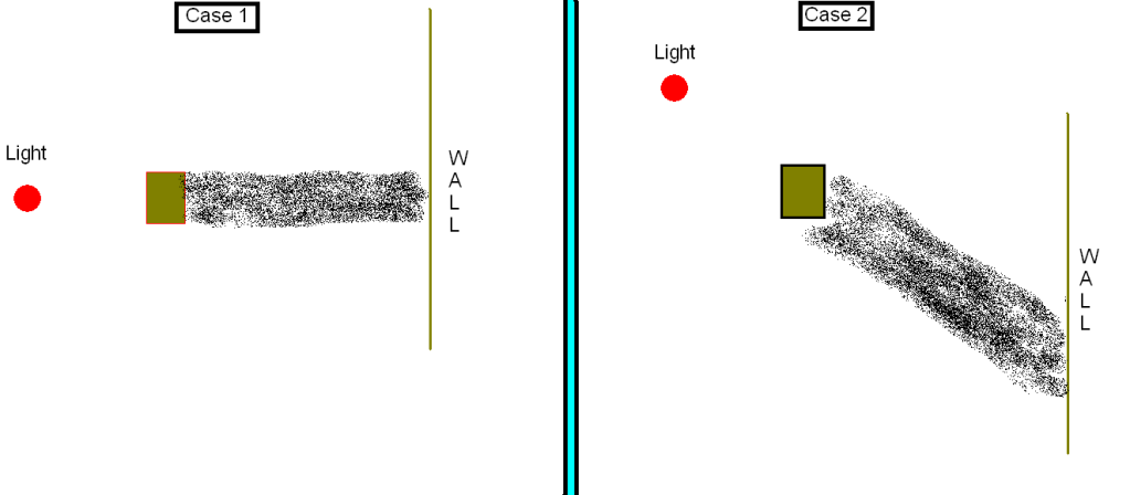
On the image i supplied, the same shadow is cast on the road surface AND the wall.
If you took a top down view, you could measure the angle of incidence between the shadow and the wall. If you took a side on view, you could measure the angle the shadow is making on the vertical surface (the wall) with respect to the horizontal plane.
Assuming I know (from a top down view again) the angle of the wall, and the angle of the shadow hitting the wall, I would like to compute the angle of the shadow on the wall from a side view.
Sorry, still too vague, need that sketch.
This sounds doable, but please avoid unrelated analogies such as “shadow” where it is a scanline, etc.
This is about math and algos, so go ahead even if this is not stricly GL related.
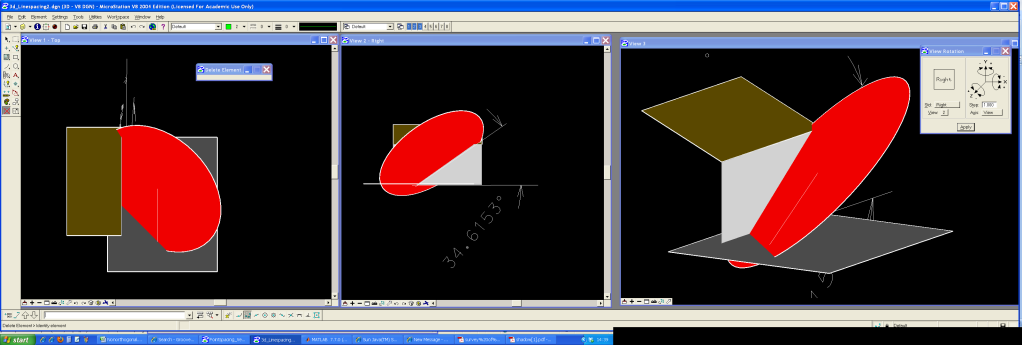
The red circle represents my circular scan laser. we have it roatated 45^ horizontal and 45^ vertical around its centre of measurement.
The image on the left represents a road, and a house at the side of the road. Its a top-down view. The red circle hits the road surface and you can see the scanline travelling along it towards the house. It hits the house at 45^.
After it hits the house at ground level, it starts to travel up the wall. The middle image represents a side on view of the scan line on the house. It is a 35^ angle, because of the way the house is rotated with respect to the scanners coordinate system.
Ive included the third isometric view for visualisation purposes hope it helps.
In case that is no clearer, ill try a shadow analogy once more. Sorry about the poor sketch.
Second is crap, but first one is very clear.
Now, what are the known values you have (angle A, B, C compared to which axis … distances … ?), and what do you want to compute with it ?
I know the angle the horizontal scan line makes with the building in the first image. Its 45^ from the y axis in the first image. Lets call that @h.
There are no fixed distances, everything is theoretical.
I would like to be able to compute the 35^ angle in the second image (i just measured it on the drawing), on the vertical surface. Lets call that @v. The surface is perfectly vertical.
In later tests I would like to be able to vary @h, and the angle of the vertical wall to represent different surfaces, sloped roofs, buildings facing away from the scanner etc. thats why i was hoping there was a general formula for how shadows react when they reach different surfaces, as it seemed similar to me.
Equation of the scan ‘line’ (which is a plane, in fact) :
n_x (x-x_0)+ n_y(y-y_0)+ n_z(z-z_0)=0
n is the normal, the direction perpendicular to the plane (rotation axis of the head)
P0: x_0,y_0,z_0 is the position of laser head, relative to the wall.
Then you have the wall plane (z up, right hand coords):
x=0
This give the following equation for the wall line
n_x (0-x_0)+ n_y(y-y_0)+ n_z(z-z_0)=0
Let’s put it in the z=Ay+B form :
-n_xx_0+ n_yy-n_yy_0+ n_zz-n_zz_0 = 0
n_zz = -n_yy+n_zz_0+n_yy_0+n_xx_0
z = -n_y/n_zy+z_0+n_y/n_zy_0+n_x/n_z*x_0
So you have :
A = -n_y/n_z
B = z_0+n_y/n_zy_0+n_x/n_zx_0
@v angle is purely determined by A, so you have : @v = arctan(A) = arctan(-n_y/n_z)
QED
By the way, this has not much to do with shadow algorithms used in computer graphics. This is pretty much an inverse problem. In computer graphics you do not compute a resulting angle, instead you sample each point to check if is in shadow or not.
Rusty too, taken straight from wikipedia page on plane equations.
Each of the n_* is a magnitude for the normal vector, for each axis.
Example, for an horizontal plane (ground), the normal vector is straight up :
n_x=0
n_y=0
n_z=1
For the vertical plane (wall in previous example), the normal vector is straight to the left, along x axis :
n_x=1
n_y=0
n_z=0
For the red plane (scanline in previous example), the normal vector does not follow a particular axis, something like :
n_x=0.5
n_y=0.5
n_z=0.7
Well normals are frequently used in computer graphics, they are very convenient. But if you prefer to work with a different expression of a direction in 3D space, ex. 2 angles theta;phi, just do as you prefer.
-when does B (from z= ay +b) get brought into the equation?
-if the wall that the scan line was hitting did not have a surface normal of 1,0,0 but a different one, say 0.5,0.5,0 how would that be integrated into the formula?
it got brought when I rewrote the wall line equation to extract A ? Not sure what is the point of the question ?
use the general plane equation (first line), and replace the n* by the new values.
You will have z = Ax+By+c
Then if you only need the angle related to the horizontal plane (like 35° on your side view), you only need B.
Hmmm…i have my two rotation matrices, and ive multiplied them. How do you know which value to chose as the surface normals? in the 45*45 one its easy, because there are only two numbers, although repeated.
In general: none. You multiply your 3x3 rotation matrix with the unit vector that corresponds to the angles (0, 0), as ZBuffeR said upthread. This applies the rotation to the vector making it point in the desired direction.
If the direction represented by angles (0,0) coincides with say the x-axis (1,0,0) this is the same as taking the first column of the rotation matrix.