Algorithm for UV cubemap warping to a sphere

I implemented a sphere with a UV cubemap. I have an algorithm that generates a cubemap sphere triangle-based mesh. The algorithm takes a parameter that drives the level of subdivision of the sphere (so I can determine the level of detail I want depending how far away the POV is).

I also implemented a straight UV mapping from the sphere coordinates to a 6-face cross-shaped texture.

Basically I am creating a cube first, with regular, uniform subdivision, then I project the coordinates onto a “normal” sphere (basically I just normalize the vertices that make the triangles that make up the cube). The cube face coordinates I use to build up the UV coordinates.

As long as the texture is matching the size and proportions that the UV mapper is expecting, I can re-use this sphere over and over again with as many textures I want.

All good and dandy.

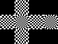
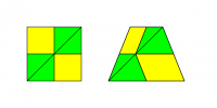
Everything works fine. Of course I am facing the issue that the textures get “warped”. They get “fish-eyed” towards the center of the face and compressed at the corners. Again … no surprises there.

What I would like to know is this: is there an algorithm that would allow me to “pre-warp” the UV coordinates, so that when the texture is sampled when it needs to render it cancels out the warping? and makes the texture looks somewhat “normal”?

People I have seen, get around by pre-warping the texture itself. However, if possible, I’d like to not have to bother with pre-warping the texture and handle it with an algorithm while I am generating the UV coordinates …

I am not sure if that’s possible. I did not find anything viable by searching … so I thought I would ask.

I have a sneaking suspicion that what I want to do is not entirely possible … I tried playing with trigonometry and vector math but I couldn’t come up with something viable … maybe my college math is a bit rusty.

Thank you!!

Although I reread your post twice, I still don’t understand what the problem is. Probably because you are using wrong terms in describing the problem.
If you want to map the sphere onto the faces of a cube, and you encountered a distortion you want to avoid, then maybe I get the point. In that case, maybe I could help.
There is a lot of spherical cube map projections. All of them have some useful properties, but none of them is both equal-area (area preserving) and conformal (shape preserving).
I wouldn’t continue any further if I completely missed the point.

It’s not entirely clear what your problem is. Simply using parametric coordinates as texture coordinates should give the same result as using a cube map, at least as the vertices. However, if the triangles are sufficiently large, you’ll run into the issue that using 2D texture coordinates results in an affine mapping, causing distortion within each triangle. That can be solved by using 4D texture coordinates (u,v,0,1)/sqrt(u^2+v^2+1), which will result in the same effective texture coordinates at the vertices but a projective mapping within the triangle.

If that doesn’t give the correct result, it’s likely that your texture isn’t mapped correctly in the first place.

For reference, a cube map for a sphere with a latitude/longitude grid should look like:

I apologize for being unclear … you are both right I am not using the correct terminology to describe my problem.

Although I think that by asking the question and trying to explain what I am looking for I am realizing I might actually be looking for something impossible.

@Aleksandar, yes you are on the right track. Basically the the texture gets distorted once projected on the sphere. The texture starts from a cube face (flat) and it gets projected on a dome, so the center gets “stretched” and the corners get “compressed”. I was looking for a an algorithm that would map UV points to the texture so that it would “pre-distort” the texture opposite to how it would be distorted once projected on the sphere and cancel out the spherical surface distortion once it renders.

There is a lot of spherical cube map projections. All of them have some useful properties, but none of them is both equal-area (area preserving) and conformal (shape preserving).

If I understand this correctly Aleksandar, I want conformal. I want to be able to generate planetary surfaces from height maps: I would like the shapes of the geographic features to not be distorted or stretched out as I look at a moving map of the surface and/or as I change altitude (since once I’m close to the surface I would select the closest tiles to the POV and only render those). I’d like the shapes to remain consistent as the spacecraft moves from orbit, to the atmosphere to low altitude.

@GClements, that texture is perfect and actually thank you for posting it. I am going to use it to test how my texture is lining up.

So … here’s why I think that what I want is not possible:

I wanted to create an algorithm so that if I wanted to paint meridians and parallels on the texture image, I could do so by drawing them STRAIGHT on the texture, the (impossible) algorithm would then map the UVs pre-distorted and bend the meridians and parallels so that once projected on the sphere the lines would appear straight again and line up with each other from face to face.

the texture uploaded by GClemens made me realize that the parallels for examples would need to come in and out of some of the faces. The parallels will never be able to be drawn straight on the texture no matter what fancy algorithm I come up with, because they’ll need to arch in and out of the face.

So I can’t make a square grid with straight lines and come up with an algorithm to make them render straight on the sphere. Will never work.

I think I am getting to the conclusion that The texture will need to incorporate distortion … (how for example the meridians are closer to each other in the center of the face and grow farther apart as they get to the edges).

… which means that if I want to create a planet earth, or any other planet with a pre-defined texture map, I will need to “distort” the map so that it matches to what GCLemens uploaded.

So … GClemens, How did you create that latitude/longitude grid map?

I hope I made more sense this time … sorry if I am not being clear and thank you for trying to help me! I really appreciate it!

The distortion is inevitable whenever you try to project surface from one shape to the other. What you should search for is not a “pre-distort” but “map projection”. It is the issue that has been bothering mankind since the ancient Greece. The surface of the Earth cannot be projected to the plane (the cube has actually 6 planes) without distortion. The two most important properties that cartographers tried to preserve are: the same size of the area on the surface of the Earth and on the projection surface (equal-area) and the same shape of the features (conformal). The conformity is actually checked by testing angles at which lines intersect after projection. If angles stay the same the projection is conformal. However, the projection cannot be both equal-area and conformal. If it preserves angles (conformal) it suffers from significant area distortion and the other way around.

Please take a look at the comparison of the spherical cube map (SCM) forward transformation. I have collected 7 most useful SCM projections and compare their properties according to the texture mapping (the paper is accepted for the publication and will be published soon). The green color depicts the absence of the distortion. Also, take a look at the effects of SCM inverse transformation. This figure shows how the regular grid from the projection space is mapped to a spherical surface.

I’m not sure that you actually need a conformal projection since it would cause a severe area distortion at the corners of the cube. In short, a conformal projection would preserve the shape, e.g. the quad would remain the quad, but its size would vary and decrease with the distance from the center of the cube face (the center of the projection). On the other hand, an equal-area projection would preserve the area, e.g. the area of the quad would be preserved wherever it is on the surface. However, the shape of the quad would not be preserved. It may not be even a rectangle. In the previous figures, aspect distortion depicts how pixels would be stretched along the axes. People usually use equal-area projections believing they will produce better mapping. Unfortunately, they produce significant aspect distortion, and, hence, require bigger textures and anisotropic filtering in order to deal with the aspect distortion.

If your texture mapping changes with the altitude, then you have some other problem. The shape of the features should not be changed with the distance from the surface. Only the anisotropy changes, but with the position on the surface, not with the height.

It sounds as if you’re looking for the “equidistant cylindrical” or “plate Carrée” projection. See e.g. wikipedia.

That’s what I’m using here. That’s raytracing the sphere with a fragment shader, but it’s possible to achieve (roughly) the same result using a mesh. Essentially, you need to convert the final 3D vertex coordinates from Euclidean coordinates (X,Y,Z) to spherical coordinates (latitude, longitude, altitude), for which the equations are (assuming that the Z axis is the planet’s axis through the poles and X=0, Y=1 is the prime meridian):


rh = sqrt(x*x+y*y);
lon = atan2(x, y);
lat = atan2(z, rh);
alt = sqrt(x*x+y*y+z*z);
s = lon / (2*M_PI) + 0.5;
t = lat / M_PI + 0.5;

The main issue with most common cartographic projections is that they have a singularity at the poles, which can result in visual artefacts in the polar regions. For most of the purposes for which maps are created, earth’s polar regions aren’t of much interest; applications which care about those regions tend to use other projections.

The main issue with using a mesh is that the mapping within each triangle isn’t affine, so you tend to get this issue:

Raytracing the sphere avoids that.

The meridians (lines of constant longitude) are vertical; it’s the parallels (lines of constant latitude) that are curved due to the edges of the cube being farther from the sphere’s centre.

Python+NumPy, then pasted together in GIMP.


import numpy as np
from matplotlib.pyplot import imsave, gray
gray()
v,u = (np.mgrid[:256,:256] - 127.5) / 128
k = np.sqrt(np.square(u)+np.square(v)+1)
xyz = np.array((u,np.ones_like(u),v))/k
r_h = np.hypot(xyz[0],xyz[1])
lon = np.arctan2(xyz[0],xyz[1])
lat = np.arctan2(xyz[2],r_h)
s = np.floor(np.degrees(lon) / 10).astype(int)
t = np.floor(np.degrees(lat) / 10).astype(int)
img = (s + t) % 2
imsave("sides.png", img)
xyz = np.array((u,v,np.ones_like(u)))/k
r_h = np.hypot(xyz[0],xyz[1])
lon = np.arctan2(xyz[0],xyz[1])
lat = np.arctan2(xyz[2],r_h)
s = np.floor(np.degrees(lon) / 10).astype(int)
t = np.floor(np.degrees(lat) / 10).astype(int)
img = (s + t) % 2
imsave("top.png", img)

Well, not most of them, just cylindrical projections (like equidistant cylindrical and Mercator). All projections that project the Earth onto a single plane have singularities, but those singularities may be elsewhere (for example, the conical projections have totally different type of singularities). The polyhedral projections tend to avoid singularities by increasing the number of projection planes. In the case of the hexahedral projections (cubes), there are six projection planes. Increasing the number of projection planes creates another problem - discontinuities (on the borders of the faces).

I’m sorry for the previous comment. GCelements gave a good explanation, but I have to make it more strict from the cartographic perspective. Probably all three of us speaking about the different aspects of the projection. When I mentioned distortion, I didn’t mean the effect of the texture coordinates interpolation across the surface of the triangle, but about the effect of projecting the spheroidal surface onto the plane. From that perspective, the proposed method has a significant, both aspect and area, distortion. I’ll rather suggest the following transformations for the front face:


// Forward transformation:
x = lon * (4/PI)
y = atan(tan(lat)/cos(phi)) * (4/PI)

// Inverse transformation:
lon = x * (PI/4)
lat = atan(tan(PI*y/4)*cos(lon))

It assumes that x,y = [-1,1] are the coordinates in the projection plane, while lon,lat=[-PI/4, PI/4] are the polar coordinates of the spherical surface.

Thank you both for getting me to look in the right direction! I will reply here if I have any further questions but I think You guys gave me a lot of excellent material to digest and mull over …

This is exactly the type of information I was looking for.

Thank you for your help!

[QUOTE=Aleksandar;1281823]Well, not most of them, just cylindrical projections (like equidistant cylindrical and Mercator).
[/QUOTE]
Right. But I believe that these are the ones which the OP is likely to be interested in.

In terms of rendering, using a cube map (in the sense of GL_TEXTURE_CUBE_MAP_*, not an “unfolded” cube as a 2D texture) avoids issues with affine texture mapping.

Conversion from a cartographic projection to a cube map is reasonably straightforward: convert texture coordinates from Cartesian to spherical coordinates to get lat/lon then convert those to whatever projection is being used (the PROJ.4 library may be of use here). Issues with extreme anisotropic scaling near the poles can be mitigated by applying a horizontal low-pass filter whose width is proportional to 1/cos(lat).

Up to my knowledge, TEXTURE_CUBE_MAP is not very useful in a plant-sized terrain rendering. Maybe TEXTURE_CUBE_MAP_ARRAY could be useful, but, on the first thought, it complicates the update greatly. That’s why I suggest using separate texture arrays for each side of the cube.

What I dislike considering the spherical cube maps is an existence of six separate datasets. That’s why it is better to group three of them into a single dataset, reducing the number of datasets to only two. NoobCoder didn’t ask for data optimization, so let’s skip the further debate on the topic. :slight_smile:

Nice suggestion! I just wanted to help which projection should be chosen. :wink:
Proj.4 has hundreds of projections, but I’m sure that the most useful SCM projections are not included.

Ah! that’s it. That’s what I was looking for. I just did it and it worked right off the bat.

Used Mercator and getting a UV map from a cubemap to a Mercator texture was unbelievably simple and effective.

This does exactly what I needed. Thank you!!!

Yes the poles are looking … “wonky” (how’s that for terminology? :wink: ) … could you elaborate on how would I apply the low pass filter and to what?

Thanks so much guys! You both have been unbelievable helpful. You really unlocked me from a heck of a problem!

here are several solutions for this problem. Texture borders solve it elegantly, but are not available on all hardware, and only exposed through the OpenGL API (and proprietary APIs in some consoles.

The vertical scale factor is constant, but the horizontal scale factor is much smaller near the poles. This tends to result in “streaks” radiating out from the poles.

To apply a horizontal low-pass filter, replace each texel in the output with a weighted average of the nearby texels in the same row. E.g. for a box filter:


#include <stdlib.h>
#include <stdio.h>
#include <math.h>

static void box_filter(double *weights, double w)
{
    double sum = 2 * floor(w) + 1;
    double k = 1.0 / sum;
    int i;
    for (i = 0; i < w; i++)
        weights[i] = k;
}

static void filter(unsigned char *out, const unsigned char *in, int width, int height)
{
#define TEX(p, x, y, c) (p)[((y)*width+((x)+width)%width)*3+(c)]

    double *weights = malloc(width * sizeof(double));
    int x, y, i;

    for (y = 0; y < height; y++) {
        double lat = M_PI * ((y + 0.5) / height - 0.5);
        double w = 0.5 / cos(lat);
        box_filter(weights, w);
        for (x = 0; x < width; x++) {
            float r = TEX(in, x, y, 0) * weights[0];
            float g = TEX(in, x, y, 1) * weights[0];
            float b = TEX(in, x, y, 2) * weights[0];
            for (i = 1; i < w; i++) {
                r += TEX(in, x-i, y, 0) * weights[i];
                r += TEX(in, x+i, y, 0) * weights[i];
                g += TEX(in, x-i, y, 1) * weights[i];
                g += TEX(in, x+i, y, 1) * weights[i];
                b += TEX(in, x-i, y, 2) * weights[i];
                b += TEX(in, x+i, y, 2) * weights[i];
            }
            TEX(out, x, y, 0) = (int) round(r);
            TEX(out, x, y, 1) = (int) round(g);
            TEX(out, x, y, 2) = (int) round(b);
        }
    }

    free(weights);
#undef TEX
}

static void error(const char *msg)
{
    fprintf(stderr, "%s
", msg);
    exit(1);
}

int main(void)
{
    int n, w, h, m;
    unsigned char *in, *out;
    if (fscanf(stdin, "P%d
", &n) != 1 || n != 6)
        error("error reading magic number");
    if (fscanf(stdin, "%d %d
", &w, &h) != 2)
        error("error reading width/height");
    if (fscanf(stdin, "%d
", &m) != 1)
        error("error reading maxval");
    n = w * h;
    in = malloc(n * 3);
    if (fread(in, 3, n, stdin) != n)
        error("error reading data");

    out = malloc(n * 3);
    filter(out, in, w, h);

    fprintf(stdout, "P6
%d %d
%d
", w, h, m);
    if (fwrite(out, 3, n, stdout) != n)
        error("error writing data");

    return 0;
}

[QUOTE=GClements;1282024]The vertical scale factor is constant, but the horizontal scale factor is much smaller near the poles. This tends to result in “streaks” radiating out from the poles.

To apply a horizontal low-pass filter, replace each texel in the output with a weighted average of the nearby texels in the same row. E.g. for a box filter:


#include <stdlib.h>
#include <stdio.h>
#include <math.h>

static void box_filter(double *weights, double w)
{
    double sum = 2 * floor(w) + 1;
    double k = 1.0 / sum;
    int i;
    for (i = 0; i < w; i++)
        weights[i] = k;
}

static void filter(unsigned char *out, const unsigned char *in, int width, int height)
{
#define TEX(p, x, y, c) (p)[((y)*width+((x)+width)%width)*3+(c)]

    double *weights = malloc(width * sizeof(double));
    int x, y, i;

    for (y = 0; y < height; y++) {
        double lat = M_PI * ((y + 0.5) / height - 0.5);
        double w = 0.5 / cos(lat);
        box_filter(weights, w);
        for (x = 0; x < width; x++) {
            float r = TEX(in, x, y, 0) * weights[0];
            float g = TEX(in, x, y, 1) * weights[0];
            float b = TEX(in, x, y, 2) * weights[0];
            for (i = 1; i < w; i++) {
                r += TEX(in, x-i, y, 0) * weights[i];
                r += TEX(in, x+i, y, 0) * weights[i];
                g += TEX(in, x-i, y, 1) * weights[i];
                g += TEX(in, x+i, y, 1) * weights[i];
                b += TEX(in, x-i, y, 2) * weights[i];
                b += TEX(in, x+i, y, 2) * weights[i];
            }
            TEX(out, x, y, 0) = (int) round(r);
            TEX(out, x, y, 1) = (int) round(g);
            TEX(out, x, y, 2) = (int) round(b);
        }
    }

    free(weights);
#undef TEX
}

static void error(const char *msg)
{
    fprintf(stderr, "%s
", msg);
    exit(1);
}

int main(void)
{
    int n, w, h, m;
    unsigned char *in, *out;
    if (fscanf(stdin, "P%d
", &n) != 1 || n != 6)
        error("error reading magic number");
    if (fscanf(stdin, "%d %d
", &w, &h) != 2)
        error("error reading width/height");
    if (fscanf(stdin, "%d
", &m) != 1)
        error("error reading maxval");
    n = w * h;
    in = malloc(n * 3);
    if (fread(in, 3, n, stdin) != n)
        error("error reading data");

    out = malloc(n * 3);
    filter(out, in, w, h);

    fprintf(stdout, "P6
%d %d
%d
", w, h, m);
    if (fwrite(out, 3, n, stdout) != n)
        error("error writing data");

    return 0;
}

[/QUOTE]

thanks much! that’s perfect!

if I figure out how to post images I will post the results here.

Thank you again for your help!