Convert to Worldspace from depth buffer

Hello! I am writing a shader which requires that I have the world-space coordinate. I need to reconstruct this position from the depth buffer, and I believe that I need to use the view and projection matrices.

Here is my current code:

vec3 reconstructWorldPosition( vec2 texCoord ) {
    float depth = getLinearDepth( texture2D(depth_buffer, texCoord).rgb );
    vec4 pos = vec4( texCoord * 2.0 - 1.0, depth * 2.0 - 1.0, 1.0 );
    pos = uInverseViewProjectionMatrix * pos;
    pos /= pos.w;
    
    return pos.xyz;
}

-texCoord is the texture coordinate of the 2d-quad rendered to the screen.
-My depth buffer is stored in linear depth using the R, G, and B components for 24-bit depth precision (I cannot use High-Precision pixel values).

However, I do not believe this is returning the correct results.

Assuming the “obvious” interpretations of [var]texcoord[/var] and [var]depth[/var], there’s nothing wrong with the code you posted, so the problem must lie elsewhere.

This is what my depth buffer currently looks like:

texCoord is just passed in as the texcoord from the vertex shader. If I output its X value to the fragcolor, it is a gradient from black to white (so it is from 0 to 1).

Here is the depth shader:

VERTEX:

attribute vec3 in_Position;

varying float linearizedDepth;

uniform float uCameraFar;
uniform float uCameraNear;

void main() {
    vec4 object_space_pos = vec4(in_Position,1.0);
    gl_Position = gm_Matrices[MATRIX_WORLD_VIEW_PROJECTION] * object_space_pos;

    linearizedDepth = (gm_Matrices[MATRIX_WORLD_VIEW] * object_space_pos).z / uCameraFar;
}

FRAGMENT:

varying float linearizedDepth;

vec3 packDepth(float f) {
    return vec3( floor( f * 255.0 ) / 255.0, fract( f * 255.0 ), fract( f * 255.0 * 255.0 ) );
}

void main() {
    float depth = linearizedDepth;
    gl_FragColor = vec4( packDepth(depth), 1.0 );
}

I am using an engine which doesn’t offer support for a proper hardware-based depth buffer, so I have to create it myself.


If I output the fragcolor to the depth (once unpacked) it is a fog from black to white (black being close to the camera).


However… I do not know what the reconstructed world coordinates should look like…

Instead of linearizing depth and storing it in an RGB8 image, have you considered sticking it in an R32F floating-point image?

As to your function (assuming that your pack/unpack works correctly), your linearized depth does not really make sense. Your linearized depth is in a normalized version of camera space. Whereas the XY positions from your texture coordinate are in NDC space. None of these are in clip space, which is the only legitimate space for multiplying by the inverse projection matrix.

There’s an OpenGL Wiki article on performing this reverse transformation, with varying degrees of information.

Unfortunately, the engine I am using doesn’t support high-precision textures; I am limited to RGBA8.

That article is quite informative! There’s a perfect section for NDC to Clip. However, I don’t have the slightest clue how to use my depth, as like you said it is in the wrong space.

However, I don’t have the slightest clue how to use my depth, as like you said it is in the wrong space.

The solution is to stop linearizing your depth. Store the actual depth, using the same space as your future shader’s XY positions (ie: NDC space). There’s nothing about your RGB8 packing function that requires a linear depth.

Unfortunately, the engine I am using doesn’t support high-precision textures; I am limited to RGBA8.

Then I have to ask the obvious question: have you considered… not using that engine? Or failing that, fixing it (I don’t know of too many commercial OpenGL-based engines that don’t give you source code)?

We’re talking about an engine that supports GLSL, but clearly lacks many of the other features that also exist around hardware that implements GLSL. Considering that it doesn’t even support floating-point textures, you’re probably lucky to get FBO support. So it’s not a particularly well conceived engine.

You’re only going to be able to do what is possible within the limitations of your engine. And if your engine doesn’t let you do what you need to, and can’t be fixed, then you need to decide which is more important: implementing this effect or using this engine. That’s not to say that it’s impossible on this engine. But considering how limited the engine is, what other failings are going to keep manifesting themselves as you continue?

[QUOTE=Alfonse Reinheart;1263782]The solution is to stop linearizing your depth. Store the actual depth, using the same space as your future shader’s XY positions (ie: NDC space). There’s nothing about your RGB8 packing function that requires a linear depth.
[/QUOTE]
I don’t know how to store non-linearized depth by hand.

This isn’t for commercial use :stuck_out_tongue: If it were, I would be using my opengl engine that I wrote in Java. The engine I am currently using is closed source unfortunately.

GLSL ES :c

Just:

  1. Ensure that your framebuffer has a depth buffer (depth texture with type GL_DEPTH_COMPONENT)
  2. Enable depth tests/writes
  3. Render with a vertex shader that writes the clip-space position to gl_Position, as usual (you’re already doing this)

Done.

Then:

  1. Feed that depth texture into a sampler2D in your 2nd pass
  2. Use PositionFromDepth_DarkPhoton() from the bottom of this post to turn that depth value back into an eye-space position

The “depth” input is the 0…1 fixed-point depth buffer value you read from your depth texture.

As I’ve said before, I don’t have access to a hardware-level depth buffer; I would need to calculate it via shader. It’s a limitation of the engine I am using for this project.

You can obtain the value from gl_FragCoord.z in the fragment shader.

Or you can just copy (gl_Position.z/gl_Position.w+1.0)/2 to a varying.

[QUOTE=GClements;1263793]You can obtain the value from gl_FragCoord.z in the fragment shader.

Or you can just copy (gl_Position.z/gl_Position.w+1.0)/2 to a varying.[/QUOTE]

what would be the purpose of adding 1 and dividing by 2? I thought that pos.z / pos.w would already be in a range from 0-1.

[EDIT]
Here is the unpacked depth buffer recorded using your method:

However it causes some visual glitches…

I don’t know how to store non-linearized depth by hand.

Which part of that are you having trouble with, getting the value or storing it? Because storing it is no different from the way you store the linearized one. It’s just a float either way.

GClements has you covered for how to get a depth value in the fragment shader. It’s also mentioned in the Wiki article.

GLSL ES :c

If you’re using OpenGL ES 2.0, you should say so up-front. I wouldn’t have bothered talking about depth or float writes (though there are perfectly good ES 2.0 extensions for that).

Or you can just copy (gl_Position.z/gl_Position.w+1.0)/2 to a varying.

That assumes a very specific depth range.

Yuck. What Engine is this? (Sorry, missed that detail.)

So I suppose you can’t glCopyTexSubImage2D from the system depth buffer either…

[QUOTE=Dark Photon;1263799]Yuck. What Engine is this? (Sorry, missed that detail.)

So I suppose you can’t glCopyTexSubImage2D from the system depth buffer either…[/QUOTE]

Yuck indeed! :slight_smile: It’s Game Maker: Studio. I got the Activation code from a friend of mine, and since I have had nothing to do as of late, I wanted to make some shaders in it :slight_smile:

It surprisingly doesn’t even use OpenGL. It actually uses DirectX, then uses Angle to convert your GLSL ES shaders to D3D equivalents.

So no, I can’t do any OpenGL functions through code :stuck_out_tongue:

After clipping, it will be in the range -1 (near plane) to +1 (far plane), whereas gl_FragCoord.z is in the range 0 (near plane) to 1 (far plane).

Did you try using gl_FragCoord.z? That’s the actual value which will be written to the depth buffer (unless the fragment shader writes to gl_FragDepth).

Also, have you checked that the functions which pack and unpack depth values to/from the texture are actually inverses of each other?

In order to fully appreciate the depth buffer, we need to first kernelize our sample colonels. Once these colonels have been occluded, we can buffer the transformed occlusion-space coordinates and achieve fully dynamic occlusion through out kernel-rotation-basis (KRB) matrix.

We can then multiply our little friend the depth colonel by the KRB matrix to transform from occlusion space back to normalized kernel space.

From here, it is easy to re-construct world space position without the steps taken. We simply have to buffer our rekernelized sample depth multiplied by our kernel-space occlusion factor (This is the inverse of the original process used to derive the occlusion value).

Here is some GLSL code which explains the process in more detail:

///////////////////////////////////////////////////////////////////////////////////////////////
uniform mat3 invKernelMatrix;
uniform vec3 linearNormalBias;
uniform mat3 KernelizedNormalMatrix;
uniform mat3 kernelMatrix;
uniform vec3 depthSampleKernel[16];

float reconstructOccludedPosition(vec3 screenSpaceCoordinates){
        // Move from screen space into normalized kernel space
       vec3 nks = invKernelMatrix * screenPos + linearNormalBias;

       // Move from NKS to occlusion space
       vec3 occlusionSpace = kernelizedNormalMatrix * nks;

       // Buffer the matrix kernel. and then re-linearize
       buffer3 bmk = linearize( buffer( kernelMatrix ));

      // finally, occlude the depth sample kernel against the buffered kernel matrix and multiply by occlusionSpace coordinate

       float occlusion = occlude( depthSampleKernel, bmk ) * occlusionSpace;

return occlusion;
}

void main(){
          // Calculate depth
          float depth = texture2D( depthBuffer, v_vTexcoord ).r;

          // Reconstruct occluded position
          float occlusion = reconstructOccludedPosition( vec3( v_vTexcoord*2.0 -1.0, 1.0));

          // Calculate world space position (By performing a normalizing sample on our newly created buffer containing the constructed occlusion positions in occlusion space. 
          //            As you know, if we multiply our occlusion factor by the depth, we can transform the coordinates back into normalized kernel space.
          //            We then rekernelize our kernel to get back to our original world space position per sample.
          //            buffer3 then takes every sample position within the kernel (we currently have 16 samples) and normalizes the result.

          vec3 world_pos = normalize( buffer3( rekernelize(depth * occlusion), 1.0 );

          // Finally we can use this information to perform the range check to avoid the haloing effect you experience in SSAO implementations.
          if( world_pos.z < depth ){
                    // sample position is occluded by something, therefore return occlusion factor
                    gl_FragColor = vec3( occlusion, 1.0 );
          } else {
                    discard; // discard the fragments if the test 
          }
}
//////////////////////////////////////////////////////////////

So once again, the process of reconstructing world space is as follows:

  • We take our screen space coordinate (texture coordinate of a fullscreen quad multiplied by 2, subtract 1 to fit into range -1 : 1).

  • Using the screen space coordinate, we calculate our coordinate in normalized kernel space (NKS) (This allows for a much more efficient method of sampling by performing a parkin’s swizzle transformation with a 4.5x performance gain over conventional sampling methods.)

  • We need to then move from NKS to occlusion space, this can easily be done by multiplying our NKS coordinate by the kernelized normal matrix.

  • Once in occlusion space (OCS), we need a sample buffer which we can apply to our NKS position. It is a simple operation to generate the sample buffer. This is achieved by first buffering the kernel matrix, this provides a basis for alternating a samples position between its previous coordinate (NKS) and its new coordinate (OCS). By doing this, we can build occlusion values.
    The buffer function simply generates a form of data-structure in which each mat3 stored in the buffer3 is bilaterally linked with all other mat3s. This allows us to make full use of hardware optimisation, a process often never used for SSAO.

  • We then linearize the buffered kernel matrix, this removes the “travelling noise” problem often seen in ssao implementations when the camera moves with low-resolution ssao buffers.

  • Now that we have our buffered kernel matrix and our occlusion space position, we can calculate the occlusion value by using the occlude(…) function and passing in our depth sample kernel and our buffered kernel matrix. This newly generated result is then multiplied by our occlusion space coordinate. This gives us an occlusion value at that point.

At this stage, we should have an approximate ssao effect, however you will notice that certain areas cast occlusion onto occluders which are far away. We also suffer from a new problem called inverse occlusion, in which convex surface begin to darken along crease lines. This is to be expected, as our occlusion process only takes into account interactions between points on geometry. The erroneous values are caused by our continuous inverse transformations.

The good news is that there is an easy way we can fix this. As you clocked on, we need world space position for this. We can construct the world position using the following process (I.E working back through our original steps, except this time as the value was buffered on the input, this will return the specific occlusion point we want in world space.)

  • normalize( buffer3( rekernelize(depth * occlusion), 1.0 );

–: As you can see from this code, we simply rekernelize the product of depth and occlusion factor, then buffer the result, and normalize.

Using this world space position, we can perform a simple depth test to ensure that only points occluded by geometry closer to the camera get occluded.

Hope this helps!

In order to fully appreciate the depth buffer, we need to first kernelize our sample colonels.

… I think something went very wrong in your automated translation program. Perhaps you can explain what “kernel” and “colonel” mean in this context?

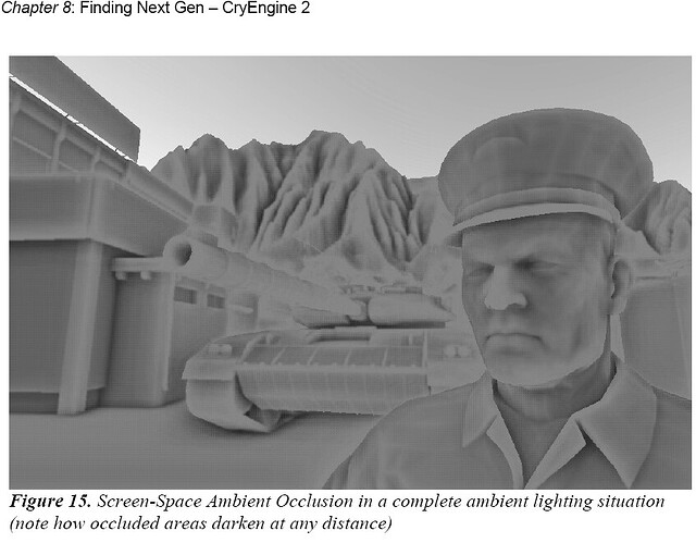
It wouldn’t let me post any images first time around, however this is what the sample colonel should look like:

This is based on the method crysis used, in which the colonel was rendered to the depth buffer, and sampled in screen space:

In order to get the sample colonel positions, we need to add on the sample kernel positions.

this is what the sample colonel should look like:

Oh, you’re talking about the content of your picture.

This is based on the method crysis used, in which the colonel was rendered to the depth buffer, and sampled in screen space:

Um, no, it isn’t. I think you’ve gotten confused with the lingo in question.

See, SSAO doesn’t care what you’re rendering. It’s just a model. The fact that it happens to be a model of a human that happens to have a military uniform on that happens to be a colonel (I’ll take your word for it) is irrelevant to SSAO. It’s just a rendering technique.

Implementing that rendering technique doesn’t require a “sample colonel”; it requires a “sampling kernel”. A completely different word with a completely different meaning that has nothing to do with what you’re actually drawing.

It also requires that you’ve rendered a mesh (or something with actual depth information). Blitting a bitmap, even of a “colonel”, is not going to get the job done.

This topic was automatically closed 183 days after the last reply. New replies are no longer allowed.